15
The measured value of the BENNING MM 8 is obtained by a mean value recti-
fication and displayed as an effective value.
The measured value of the BENNING MM 9/ 10 is obtained as a real effective
value (TRUE RMS) and then displayed.
*1
The measuring accuracy is specified for sinusoidal curves and is valid for
indicating values below 4000 digits. For indicating values higher than 4000
digits 0.6 % have to be added to the specified measuring accuracy. In case
of non-sinusoidal curves below 2000 digits, the indicating value becomes
inaccurate. Thus, an additional error occurs for the following crest factors:
crest factor from 1.4 to 3.0 additional error ± 1.5 %
*2
valid for sinusoidal curves 50 Hz/ 60 Hz
7.3 Direct current ranges
overload protection:
- 600 V
eff
at the µA input,
- 10 A (500 V) fuse, quick-acting, at the 10 A input (BENNING MM 9/ 10),
Measuring
range
Resolution Meas. precision Voltage drop
600 µA 0,1 µA
± (1.0 % of the measured value + 2 digits)
< 4 mV/ µA
6000 µA 1 µA
± (1.0 % of the measured value + 2 digits)
< 4 mV/ µA
6 A 1 mA
± (1.0 % of the measured value + 2 digits)
2 V max.
10 A 10 mA
± (1.0 % of the measured value + 2 digits)
2 V max.
7.4 Alternating current ranges (BENNING MM 9/ 10)
overload protection:
- 10 A (500 V) fuse, quick-acting, at the 10 A input (BENNING MM 9/ 10),
Measuring
range
Resolution
Meas. precision
*1
within the
frequency range 50 Hz - 500 Hz
Voltage drop
6 A 1 mA
± (1.5 % of the measured value + 5 digits)
2 V max.
10 A 10 mA
± (1.5 % of the measured value + 5 digits)
2 V max.
The measured value of the BENNING MM 8 is obtained by a mean value recti-
fication and displayed as an effective value.
The measured value of the BENNING MM 9/ 10 is obtained as a real effective
value (TRUE RMS) and then displayed.
*1
The measuring accuracy is specified for sinusoidal curves and is valid for
indicating values below 4000 digits. For indicating values higher than 4000
digits 0.6 % have to be added to the specified measuring accuracy. In case
of non-sinusoidal curves below 2000 digits, the indicating value becomes
inaccurate. Thus, an additional error occurs for the following crest factors:
crest factor from 1.4 to 3.0 additional error ± 1.5 %
7.5 Resistance measuring ranges
Overload protection in the case of resistance measurements: 600 V
eff
Measuring
range
Resolution Meas. precision
Max. idling
voltage
600 Ω 0,1 Ω
± (0.7 % of the measured value + 2 digits)
1,3 V
6 kΩ 1 Ω
± (0.7 % of the measured value + 2 digits)
1,3 V
60 kΩ 10 Ω
± (0.7 % of the measured value + 2 digits)
1,3 V
600 kΩ 100 Ω
± (0.7 % of the measured value + 2 digits)
1,3 V
6 MΩ 1 kΩ
± (0.7 % of the measured value + 2 digits)
1,3 V
60 MΩ 10 kΩ
± (0.7 % of the measured value + 2 digits)
1,3 V
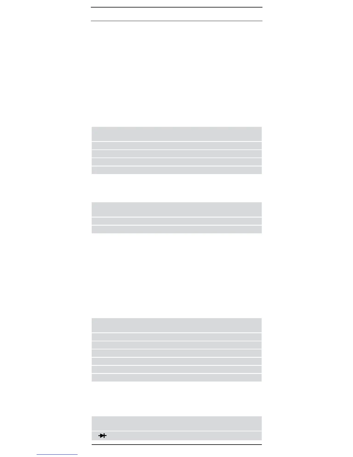
7.6 Diode and continuity testing
The indicated measurement precision applies in the range between 0.4 V and
0.8 V.
Overload protection for diode testing: 600 V
eff
The built-in buzzer sounds in the case of a resistance R less than 100 Ω.
Meas.
range
resolu-
tion
Meas. precision
Max. meas.
current
Max. idling
voltage
10 mV
± (1.5 % of the measured value + 5 digit)
1,5 mA 3,0 V
11/ 2006
BENNING MM 8/ 9/ 10
 Loading...