Switch mode, single-phase, sine-wave Inverter
Product line TEBEVERT
August 8, 2005 - DTL 11/21 No. 4219en R2
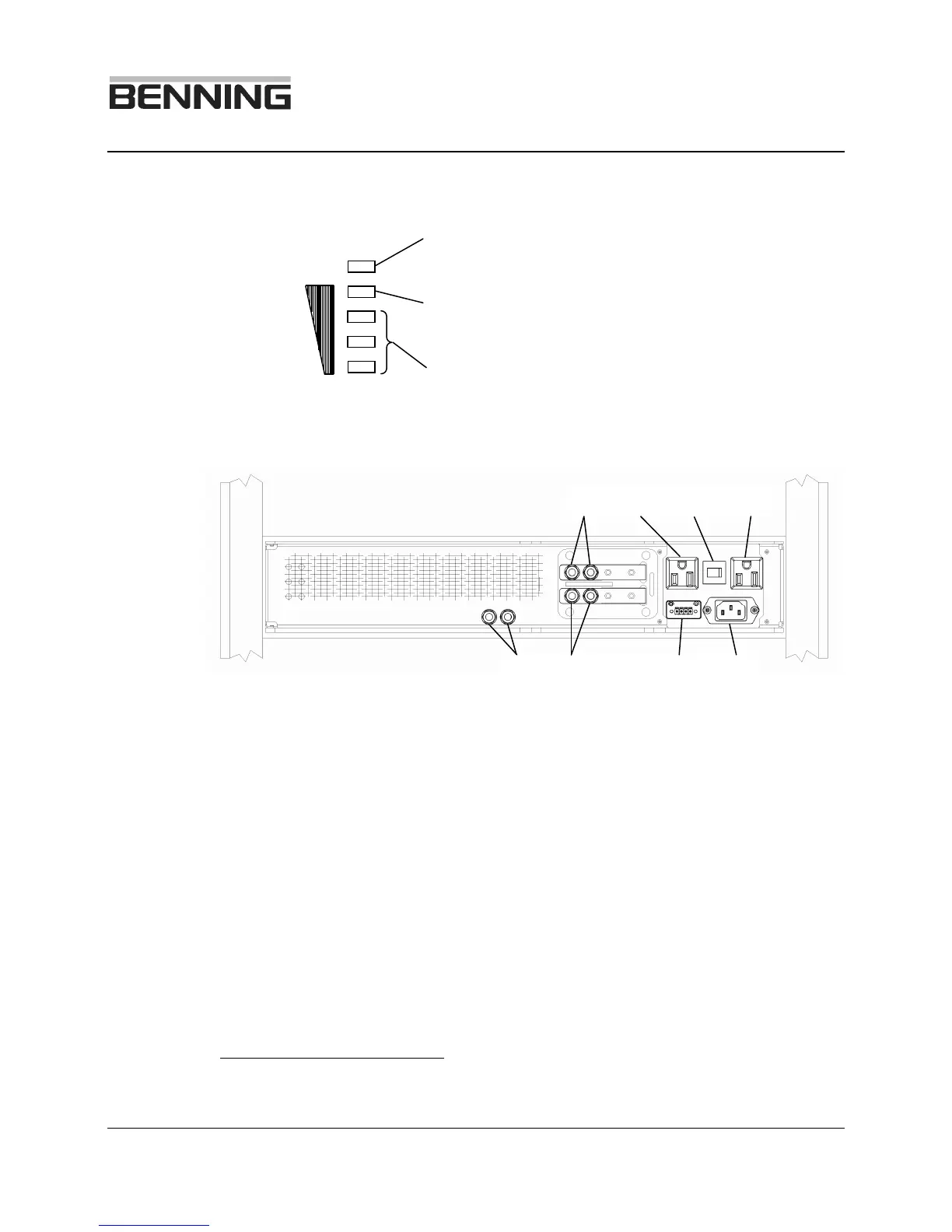
3 LED’s for signalling the actual inverter output power
The inverter is overloaded if the LED is flashing
(RED)
When this LED is lit the inverter is loaded nearly to
the limit (YELLOW)
The lit LED’s indicate the approximate load level
(Green)
Fig. 4: Rear view of the inverter
1 X1(+); Copper bar / threaded stud; plus (+) connection for the DC input
of the inverter. Arranged for ¼” x 5/8”, two-hole crimp lug
2 X3; inverter output receptacle No. 2, 5-15 R. * 12033X-HW1 has a
terminal block for hardwired output in this position.
1
3 F1; thermal over current trip circuit breaker
4 X4; inverter output receptacle No. 1, 5-15 R
5 X2; Commercial AC bypass input IEC-320 (Cord not included)
1
12033X-HW1: 12 AWG cable is the max allowable cable size