100
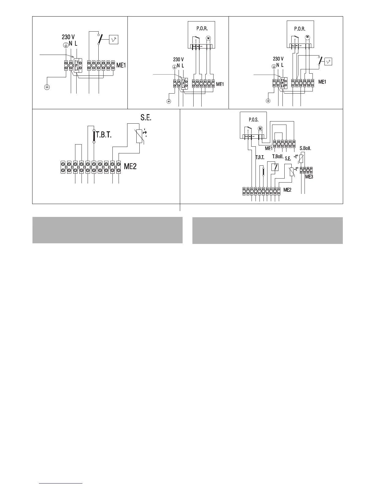
CONNEXION DU THERMOSTAT D’AMBIANCE
ET/OU DU PROGRAMMATEUR HORAIRE
(C.A.I.-MIX C.S.I.-R.A.I.-MIX R.S.I.)
Français
a Le thermostat d’ambiance doit être placé de la façon indiquée sur le
schéma après avoir ôté le cavalier placé sur le bornier à 6 pôles. Les
contacts du thermostat d’ambiance doivent être dimensionnés pour
V= 230 Volt.
1= 2AF fusible
b Le programmateur horaire de chauffage doit être placé de la façon
indiquée sur le schéma après avoir ôté le cavalier du thermostat
d’ambiance placé sur le bornier à 6 pôles. Les contacts du
programmateur horaire doivent être dimensionnés pour V= 230 Volt.
1= 2AF fusible
c Le programmateur horaire de chauffage et le thermostat d’ambiance
doivent être placés de la façon indiquée sur le schéma après avoir ôté
le cavalier placé sur le bornier à 6 pôles. Les contacts du thermostat
d’ambiance et du programmateur doivent être dimensionnés pour V=
230 Volt.
1= 2AF fusible
d Les usagers de basse tension doivent être branchés de la façon
indiquée par la figure sur le bornier ME2 prévu pour le branchement
des usagers en basse tension.
T.B.T. = Thermostat basse température
S.E. = Sonde extérieure
e Les usagers de basse tension doivent être branchés de la façon
indiquée par la figure sur le bornier ME2 prévu pour le branchement
des usagers en basse tension.
T.B.T. = Thermostat basse température
S.E. = Sonde extérieure
P.O.S. = Programmateur horaire sanitaire
T. Boll. = Thermostat ballon
S. Boll. = Sonde ballon
ab c
C.A.I. - MIX C.S.I.
R.A.I. - MIX R.S.I.
CONNECTING THE AMBIENT THERMOSTAT
AND/OR TIME CLOCK
(C.A.I.-MIX C.S.I.-R.A.I.-MIX R.S.I.)
English
a Fit the ambient thermostat as shown in the diagram after removing the
jumper on the 6-pin terminal board.
The ambient thermostat contacts must be suitable for V= 230 Volt.
1= 2AF fuse
b Fit the heating time clock as shown in the diagram after removing the
jumper on the 6-pin terminal board.
The heating time clock contacts must be suitable for V= 230 Volt.
1= 2AF fuse
c Fit the heating time clock and the smbient thermostat as shown in the
diagram after removing the jumper on the 6-pin terminal board.
The ambient thermostat and heating time clock contacts must be
suitable for V= 230 Volt.
1= 2AF fuse
d Fit low voltage connections as shown in figure on the board ME2
previewed for low voltage connections.
T.B.T. = Low temperature thermostat
S.E. = External sensor
e Fit low voltage connections as shown in figure on the board ME2
previewed for low voltage connections.
T.B.T. = Low temperature thermostat
S.E. = External sensor
P.O.S. = DHW time clock
T. Boll. = Water tank thermostat
S. Boll. = Water tank sensor
C.A.I. - MIX C.S.I.
R.A.I. - MIX R.S.I.
1
C.A.I. - MIX C.S.I.
R.A.I. - MIX R.S.I.
2
1
C.A.I. - MIX C.S.I.
de
R.A.I. - MIX R.S.I.
2
1
 Loading...