14
Fig. 34
Fig. 35
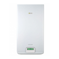
Info 2 shows circuit pressure (fig. 31)
Info 3 shows the set heating temperature (fig. 32)
Info 4 shows the set domestic hot water temperature (fig. 33).
S.A.R.A. function
If the “winter” mode is selected, the S.A.R.A. (Automatic Ambient
Adjustment System) function can be activated.
Turn the heating water temperature selector to a temperature
ranging between 55 and 65 °C.
The S.A.R.A. self-adjustment system activates: depending on the
temperature set on the ambient thermostat and the time taken to
reach it, the boiler automatically adjusts the heating water tem-
perature to reduce operating times, thereby increasing operating
comfort and energy saving.
Fig. 31
Fig. 32
Fig. 33
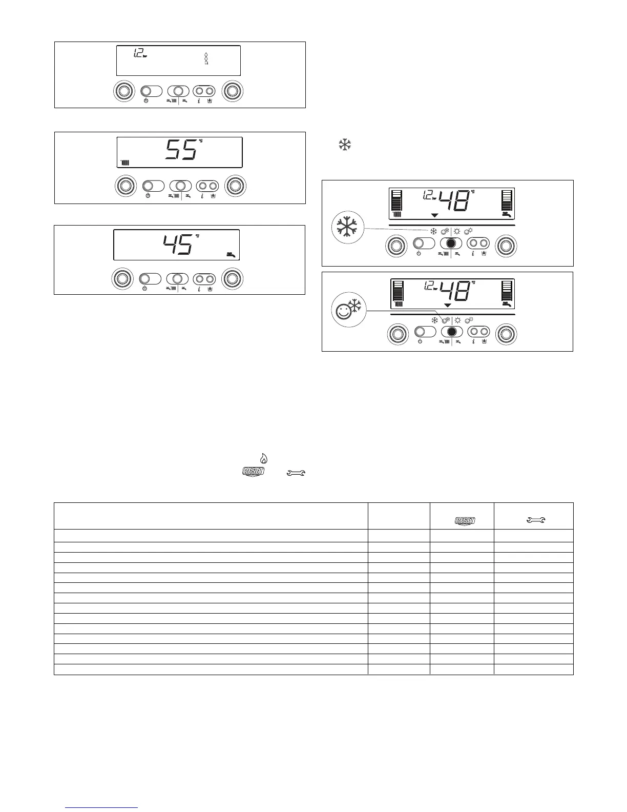
S.A.R.A. BOOSTER function
If the “winter comfort” mode is selected, the S.A.R.A. Booster
function is activated for the heating circuit and reaches the required
ambient temperature more quickly.
DOMESTIC HOT WATER PRE-HEATING function
If the “winter comfort” mode is selected, the domestic hot water
Preheating function is enabled. This function sets out to keep the
domestic hot water contained in the boiler hot, thereby considerably
reducing delivery waiting times.
The
function should be selected to reduce power consumption
in areas where the mains water is not particularly cold.
In this case, the Booster and Preheating functions are not activated.
Troubleshooting
When a fault appears on the display, the flame symbol goes out,
a flashing code is shown and the two symbols
and
appear either together or separately.
For a description of the faults, consult the following table
.
(D) Permanent
(T) Temporary. In this operating status the boiler attempts to eliminate the fault on its own
(°) See NOTE in the next page.
(*) For the “insufficient circuit pressure” fault, proceed with the circuit filling operations described in the “Boiler functions” chapter.
FAULT Alarm Symbol Symbol
ID
FLAME FAILURE BLOCK (D) 10 YES NO
LIMIT THERMOSTAT (D) 20 YES NO
BURNER THERMOSTAT (D) (MIX C.S.I) 21 YES NO
FUMES THERMOSTAT (D) (C.A.I.) 22 YES YES
FUMES OUTLET OR AIR PRESSOSTAT (D) (MIX C.S.I.) 30 YES NO
FUMES OUTLET OR AIR PRESSOSTAT (T) (MIX C.S.I.) 31 NO YES
INSUFFICIENT SYSTEM PRESSURE (D*) 40 YES NO
INSUFFICIENT SYSTEM PRESSURE (T*) 41 NO YES
WATER PRESSURE TRANSDUCER (D) 42 YES YES
FALSE FLAME (D) 50 YES YES
ELECTRONIC BOARD (D) 51-59 YES YES
SANITARY PROBE 1 (T°) 60 NO YES
PRIMARY PROBE (T) 71 NO YES
LOW TEMPERATURE THERMOSTAT (T) 77 YES YES
 Loading...