8
MYNUTE X
30C
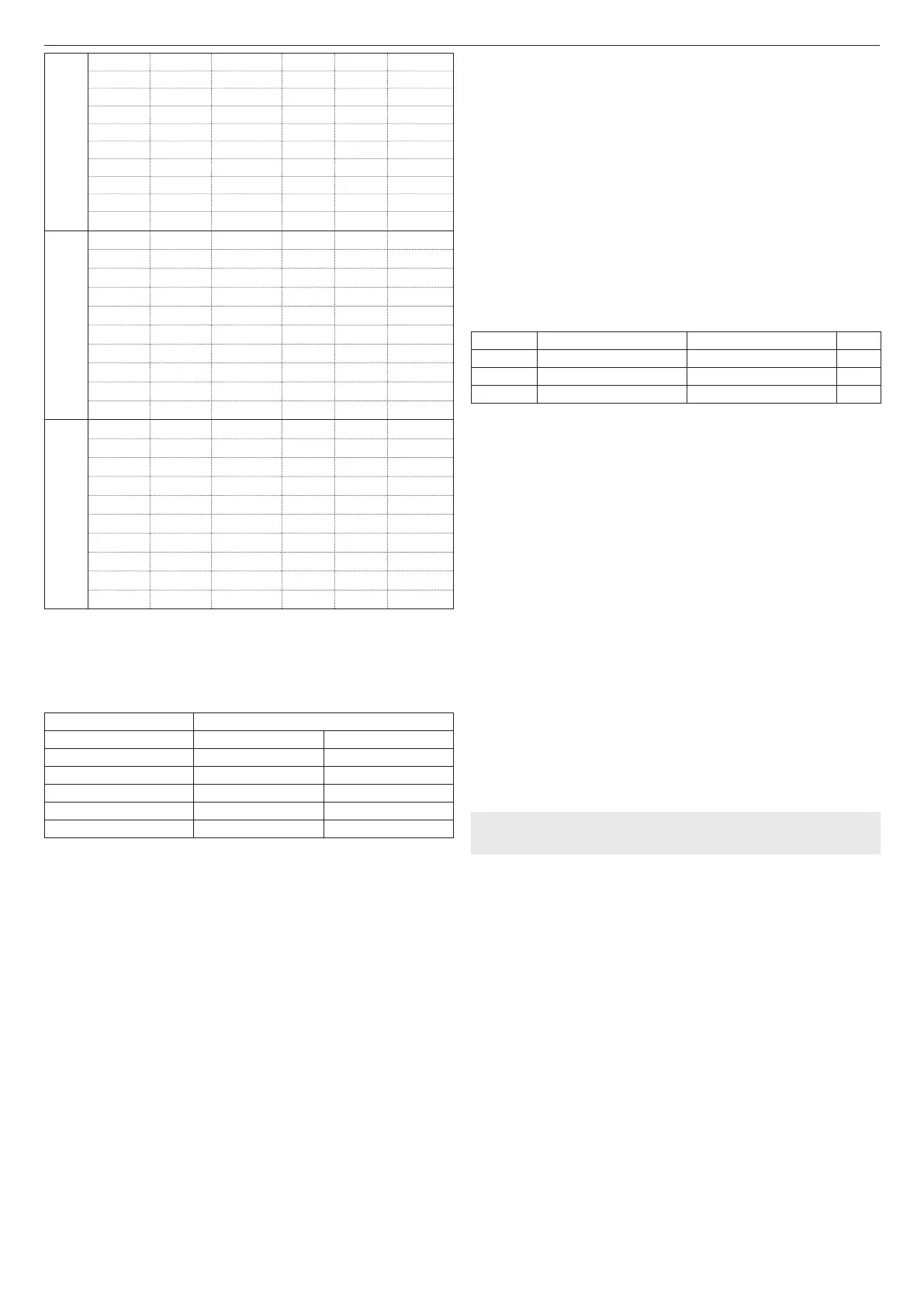
5,800 6,900 2 11 53 150
5,900 7,000 4 15 73 189
6,000 7,100 5 (*) 19 (*) 93 (*) 229
6,100 7,200 7 (*) 24 (*) 113 (*) 268
6,200 7,300 9 (*) 28 (*) 133 (*) 308
6,300 7,400 10 (*) 32 (*) 153 (*) 347
6,400 7,500 12 (*) 36 (*) 173 (*) 386
6,500 7,600 14 (*) 40 (*) 193 (*) 426
6,600 7,700 16 (*) 44 (*) 214 (*) 465
6,700 7,800 17 (*) 49 (*) 234 (*) 504
35C
6,900 7,800 2 11 57 190
7,000 7,900 3 (*) 15 (*) 75 (*) 229
7,100 8,000 4 (*) 19 (*) 93 (*) 269
7,200 8,100 6 (*) 22 (*) 112 (*) 308
7,300 8,200 7 (*) 26 (*) 130 (*) 348
7,400 8,300 9 (*) 30 (*) 148 (*) 387
7,500 8,400 10 (*) 33 (*) 166 (*) 426
7,600 8,500 12 (*) 37 (*) 184 (*) 466
7,700 8,600 13 (*) 40 (*) 202 (*) 505
7,800 8,700 15 (*) 44 (*) 220 (*) 544
40C
6,900 9,100 not applicable 7 42 196
7,000 9,200
not applicable (*)
10 (*) 60 (*) 235
7,100 9,300 1 (*) 13 (*) 78 (*) 275
7,200 9,400 3 (*) 16 (*) 96 (*) 314
7,300 9,500 4 (*) 19 (*) 114 (*) 354
7,400 9,600 5 (*) 23 (*) 138 (*) 393
7,500 9,700 7 (*) 26 (*) 156 (*) 432
7,600 9,800 8 (*) 29 (*) 174 (*) 472
7,700 9,900 9 (*) 32 (*) 192 (*) 511
7,800 10,000 10 (*) 35 (*) 210 (*) 550
(*) Maximum length that can be installed ONLY with class H1 discharge pipes.
The Ø50 or Ø60 or Ø80 congurations contain Lab test data. In the event of installations that
differ from the indications in the “standard congurations” and “adjustments” tables, refer to
the equivalent linear lengths below.
b
In any case, the maximum lengths declared in the booklet are guaranteed, and it is
essential not to exceed them.
Linear equivalent in metres Ø80 (m)
COMPONENT Ø 50 COMPONENT Ø 60
Bend 45° 12.3 5
Bend 90° 19.6 8
Extension 0.5m 6.1 2.5
Extension 1.0m 13.5 5.5
Extension 2.0m 29.5 12
3.15 Installation on collective ues in positive pressure (g 18)
The collective ue is a ue gas exhaust system suitable for collecting and expelling the
combustion products of several appliances installed on several oors of a building.
The positive pressure collective ues can only be used for type C condensing appliances.
Therefore the B53P/B23P conguration is forbidden. The installation of boilers under
collective pressure ues is allowed exclusively in G20.
The boiler is sized to operate correctly up to a maximum internal pressure of the ue no
higher than the value of 25 Pa. Check that the fan speed corresponds to what is shown in
the table "technical data".
Make sure that the air intake and exhaust pipes of the combustion products are watertight.
WARNINGS:
b
The appliances connected to a collective pipe must all be of the same type and have
equivalent combustion characteristics
.
b
The number of devices connected to a positive pressure collective pipe is dened
by the ue designer
.
The boiler is designed to be connected to a collective ue sized to operate in conditions
where the static pressure of the collective ue pipe can exceed the static pressure of the
collective air duct of 25 Pa in the condition in which n-1 boilers work at maximum rated heat
input and 1 boiler at the minimum rated heat input allowed by the controls.
b
The minimum permissible pressure difference between the ue gas outlet and the
combustion air inlet is -200 Pa (including - 100 Pa of wind pressure)
.
For both types of exhaust, further accessories are available (curves, extensions, terminals,
etc.) which make possible the ue gas exhaust congurations foreseen in the boiler booklet.
b
The pipes must be installed in such a way as to avoid condensation sticking which
would prevent the correct evacuation of the combustion products
.
b
A data plate must be present at the connection point with the collective ue pipe. The
plate must include at least the following information:
- the collective ue is sized for boilers C(10) type
- the maximum permissible mass ow of the combustion products in kg/h
- the dimensions of the connection to the common pipes
- a warning concerning the openings for the air outlet and the entry of the combu-
stion products of the collective pressure pipe; these openings must be closed
and their tightness must be checked when the boiler is disconnected
- the name of the manufacturer of the collective smoke pipe or its identication
symbol.
b
See applicable legislation for the discharge of the combustion products as well as
local regulations.
b
The ue gas pipe must be suitably selected based on the parameters shown below
.
maximum length minimum length UM
ø 60-100 4,5 0,5 m
ø 80 4,5 0,5 m
ø 80/125 4,5 0,5 m
b
The terminal of the collective pipe must generate an upward air current.
b
Before attempting any operation, disconnect the appliance from the electrical supply.
b
Before assembling, lubricate the gaskets with a non-corrosive glide lubricant.
b
The ue gases discharge pipe should be inclined, if the pipe is horizontal, by 3°
towards the boiler.
b
The number and characteristics of the exhaust ventilation devices which are the real
characteristics of the ue itself.
b
The condensation can ow inside the boiler.
b
The maximum recirculated value allowed in wind conditions is 10%.
b
The maximum permissible pressure difference (25 Pa) between the combustion
products inlet and the air outlet of a collective ue can not be exceeded when-
1 boiler work at the maximum nominal heat output and 1 boiler within minimum
temperature allowed by the checks.
b
The collective smoke pipe must be adequate for an overpressure of at least 200 Pa.
b
The collective ue must not be equipped with a wind-proong device.
At this point it is possible to install the curves and extensions, available as accessories,
depending on the type of installation desired.
The maximum permissible lengths of the ue pipe and the air intake pipe are given in the
instruction manual of the reference device (g 18a-18b).
With C(10) installation, in any case, report the number of fan speed (rpm) on the
label placed next to the data plate.
Installation currently not available on model 40kW.

 Loading...