92
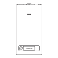
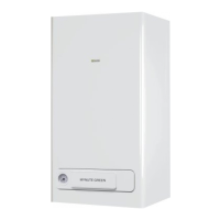
MYNUTE X
[EN] - Multiwire wiring diagram
“L-N” POLARITY IS RECOMMENDED
Blu=Blue Marrone=Brown
Nero=Black Rosso=Red
Bianco=White Viola=Violet
Rosa=Pink Arancione=Orange
Grigio=Grey Giallo=Yellow
Verde=Green
A = Gas valve
B = 230V auxiliary
D = Voltage free contact input
AKM0X Control board
SCxx Display board
BE20 Board led:
green led (operating status or temporary
shutdown)
red led (boiler in block)
X1-X25-CN1
Connection connectors
S.W.1 Chimney sweep and interruption of the vent
cycle
E.R. Flame detection electrode
F External fuse 3.15A F
F2 Fuse 4A T
M3-M4 Terminal board for external connections: 230V
CE4 Removable ModBus connector under the shelf
for external connections:
(- A B +) Bus 485
CE8 Removable connector under the shelf for
external connections:
TBT: Low temperature limit thermostat
TA: Room thermostat (contact must be free of
voltage)
OT+: Open therm
SE: Outdoor temperature sensor
P Pump
PWM PWM signal pump modulation
OPE Gas valve operator
V Hv Fan power supply 230 V
TSC2 Ignition transformer
E.A. Ignition electrode
T.L.A. Water limit thermostat
S.F. Flue gas probe
S.M. Temperature ow sensor on primary circuit
S.R. Temperature return sensor on primary circuit
F.L. Domestic hot water ow switch
S.S. Domestic hot water circuit temperature probe
T.P. Pressure transducer
MOD Modulator
V Lv Fan control signal
3V 3-way valve stepper servomotor
[ES] - Esquema de conexiones
“L-N” SE RECOMIENDA LA POLARIZACIÓN
Blu=Azul Marrone=Marrón
Nero=Negro Rosso=Rojo
Bianco=Blanco Viola=Violeta
Rosa=Rosa Arancione=Naranja
Grigio=Gris Giallo=Amarillo
Verde=Verde
A = Válvula del gas
B = 230V auxiliar
D = Entrada de tensión sin contacto
AKM0X Panel de control
SCxx Panel gráco
BE20 Led de tarjeta:
led verde (en funcionamiento o temporalmente
apagado)
led rojo (caldera en bloqueo)
X1-X25-CN1
Conectores
S.W.1 Deshollinador e interrupción del ciclo de
purgado
E.R. Electrodo de detección
F Fusible externos 3.15A F
F2 Fusible 4A T
M3-M4 Tablero de bornes para las conexiones externas:
230V
CE4 Conector extraíble ModBus colocado debajo del
estante:
(- A B +) Bus 485
CE8 Conector extraíble colocado debajo del estante:
TBT: Termostato de límite de temperatura baja
TA: Termostato ambiente (contacto debe estar
sin tensión)
OT+: Open therm
SE: Sensor de temperatura externa
P Bomba
PWM Bomba modulante
OPE Operador válvula del gas
V Hv Alimentación de potencia del ventilador HV 230V
TSC2 Transformador de encendido
E.A. Electrodo de encendido
T.L.A. Termostato límite exceso de temperatura del agua
S.F. Sonda humos
S.M. Sensor de temperatura de entrega del circuito
primario
S.R. Sensor de temperatura de retorno del circuito
primario
F.L. Caudalímetro
S.S. Sensor de temperatura del circuito de agua
caliente sanitaria (NTC)
T.P. Transductor de presión
MOD Modulador
V Lv Alarma de control del ventilador
3V Servomotor de la válvula solenoide de tres vías
[RO] - Schema electrică multilară
ESTE RECOMANDATĂ POLARITATEA „L-N”
Blu=Albastru Marrone=Maron
Nero=Negru Rosso=Roşu
Bianco=Alb Viola=Violet
Rosa=Roz Arancione=Portocaliu
Grigio=Gri Giallo=Galben
Verde=Verde
A = Vană de gaz
B = 230V auxiliar
D = Intrare contact fără tensiune
AKM0X Placă de comandă
SCxx Placă de aşare
BE20 Led placă:
led verde (funcţionare sau oprire temporară)
led roşu (centrală termică oprită)
X1-X25-CN1
Conectori de cuplare
S.W.1 Curăţare coş de fum şi întreruperea ciclului de
aerisire
E.R. Electrod de relevare acără
F Siguranţă externă 3,15A F
F2 Siguranţă 4A T
M3-M4 Placă cu borne pentru conexiuni externe: 230 V
CE4 Conector amovibil ModBus sub raft pentru
conexiuni externe:
(- A B +) Magistrală 485
CE8 Conector amovibil sub raft pentru conexiuni
externe:
TBT: Termostat limită temperatură scăzută
TA: Termostat de cameră (contactul trebuie să
nu e sub tensiune)
OT+: Term. în aer liber
SE: Senzor de temperatură externă
P Pompă
PWM semnal PWM modulare pompă
OPE Operator supapă gaz
V Hv Sursă alimentare ventilator 230 V
TSC2 Transformator de aprindere
E.A. Electrod de aprindere
T.L.A. Termostat de limitare apă
S.F. Sondă fum
S.M. Senzor de debit temperatură pe circuitul principal
S.R. Senzor de temperatură la retur pe circuitul
principal
F.L. Fluxostat sanitar
S.S. Sondă temperatură circuit apă caldă menajeră
T.P. Traductor de presiune
MOD Modulator
V Lv Semnal control ventilator
3V Servomotor pas cu pas vană cu 3 căi
 Loading...


