i The specification of the function as an input/output is dependent on the ETS programming.
picture 4
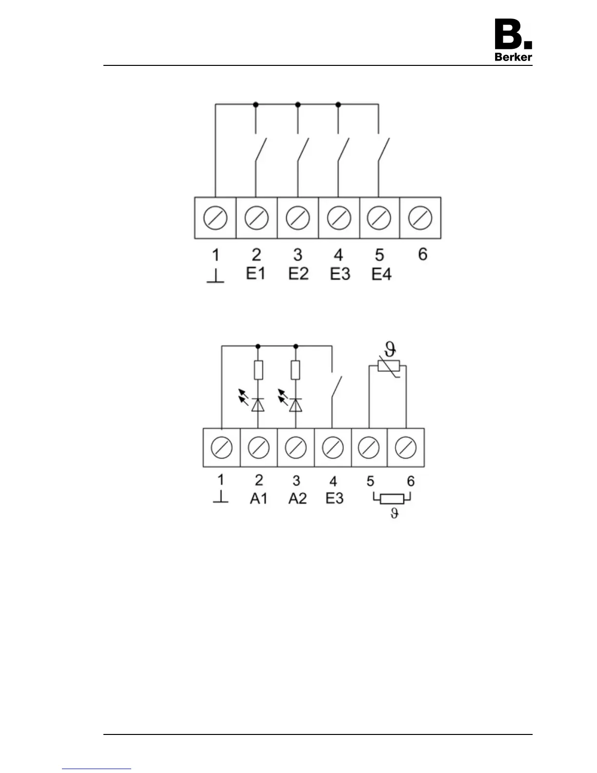
picture 5
Optional: Route an external temperature sensor in an empty pipe and run the sensor head out
at the measurement location.
Select the installation location for the temperature sensor so that it can measure the
temperature without influence from sources of interference.
o Connect the external temperature sensor to the terminals 5 and 6 (picture 5) of the terminal
strip (10) (picture 3).
i The sensor cable can be extended up to a maximum of 50 m with a a twisted pair cable, e.
g. J-Y(St)Y-2x2x0.8. When using the KNX bus cable: Use a second pair of cores, yellow-
white.
o Insert terminal insert (4) (picture 2) in flush-mounted appliance box. Note label OBEN /
TOP. The bus connection (11) must be to the right (picture 3).
o Fit design frame (5) on terminal insert (4) (picture 2).
o Insert the electronics cover (6) into the terminal insert (4) in the correct orientation
(picture 2).
Seite 5/6
23.07.2010
825 619 21
97-09605-000
KNX
KNX thermostat