Electrical 7
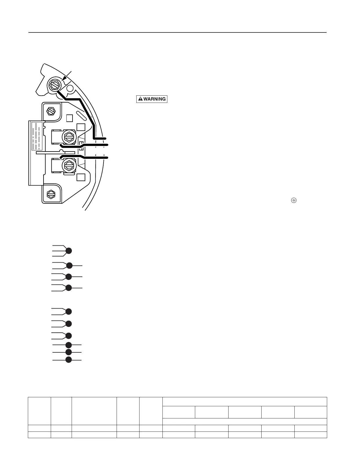
Connection Diagram for Single-Phase Motors
Your motor’s terminal board (under the motor end cover) should match the
diagram in Figure 12A or 12B.
For single-phase motors, follow Figure 12A. For 3-phase motors, follow
Figure 12B. If motor does not match this picture, follow the connection
diagram on the motor nameplate or in the motor connection box.
Hazardous voltage. Can shock, burn, or cause death.
Disconnect power to motor before working on pump or motor. Ground
motor before connecting to power supply.
1. Install, ground, wire and maintain this pump in accordance with electri-
cal code requirements. Consult your local building inspector for infor-
mation about codes.
2. Provide a correctly fused disconnect switch for protection while working on
motor. Consult local or national electrical codes for switch requirements.
3. Disconnect power before servicing motor or pump. If the disconnect
switch is out of sight of pump, lock it open and tag it to prevent unex-
pected power application.
4. Ground the pump permanently using a wire of the same size as that
specified in wiring chart (below). Make ground connection to green
grounding terminal under motor canopy marked GRD. or .
5. Connect ground wire to a grounded lead in the service panel or to a
metal underground water pipe or well casing at least 10 feet long. Do
not connect to plastic pipe or insulated fittings.
6. Protect current carrying and grounding conductors from cuts, grease,
heat, oil, and chemicals.
7. Connect current carrying conductors to terminals L1 and L2 under
motor canopy (single phase) or in motor connection box (3-phase).
When replacing motor, check wiring diagram on motor nameplate
against Figures 12A and 12B. If the motor wiring diagram does not
match one of the diagrams in Figures 12A and 12B, follow the diagram
on the motor.
8. Motor has automatic internal thermal overload protection. If motor has
stopped for unknown reasons, thermal overload may restart it unex-
pectedly, which could cause injury or property damage. Disconnect
power before servicing motor.
9. If this procedure or the wiring diagram is confusing, consult a licensed
electrician.
Figure 12A – 230V Single Phase
Wiring Diagram
Wiring Chart – Recommended Wire and Fuse Sizes
Branch
DISTANCE IN FEET(METERS) FROM MOTOR TO SUPPLY
Service Fuse
0 - 100 101 - 200 201 - 300 301 - 400 401 - 500
Motor
Factor Rating
(0 - 30) (31 - 61) (62 - 91) (92 - 122) (123 - 152)
Model HP Volts/Hz/Phase Amp Amp AWG WIRE SIZE (mm
2
)
B82456 2 230/60/1 13.3 20 12 (3) 12 (3) 10 (5.5) 10 (5.5) 8 (8.4)
B82639 2 208-230/460/60/3 11.0/5.5 15/15 14 (2)/14 (2) 14 (2)/14 (2) 12 (3)/14 (2) 10 (5.5)/14 (2) 10 (5.5)/14 (2)
leads.
 Loading...