Maintenance 9
MAINTENANCE
If motor is replaced, replace the shaft seal and O-Rings. Keep a seal and
O-Rings on hand for future use.
Be sure to prime pump before starting.
NOTICE: The mechanical shaft seal in the pump is water lubricated and
self-adjusting.
NOTICE: Drain pump (see Figure 16) when disconnecting from service or
when it might freeze. You can fill the pump with RV anti-freeze (propylene
glycol) to prevent it from freezing. DO NOT remove the Recirculation
Valve to drain the pump (Figure 16). Remove the hex head plug on the
bottom of the Pump Suction Body to drain the pump.
PUMP DISASSEMBLY
See Exploded View, Page 12, for Key No. References.
NOTICE: Do not disturb the recirculation valve (see Figure 16). It is NOT a
drain plug!
1. Shut off power to the pump before working on it.
2. Close all suction and discharge valves to isolate the pump before pro-
ceeding further.
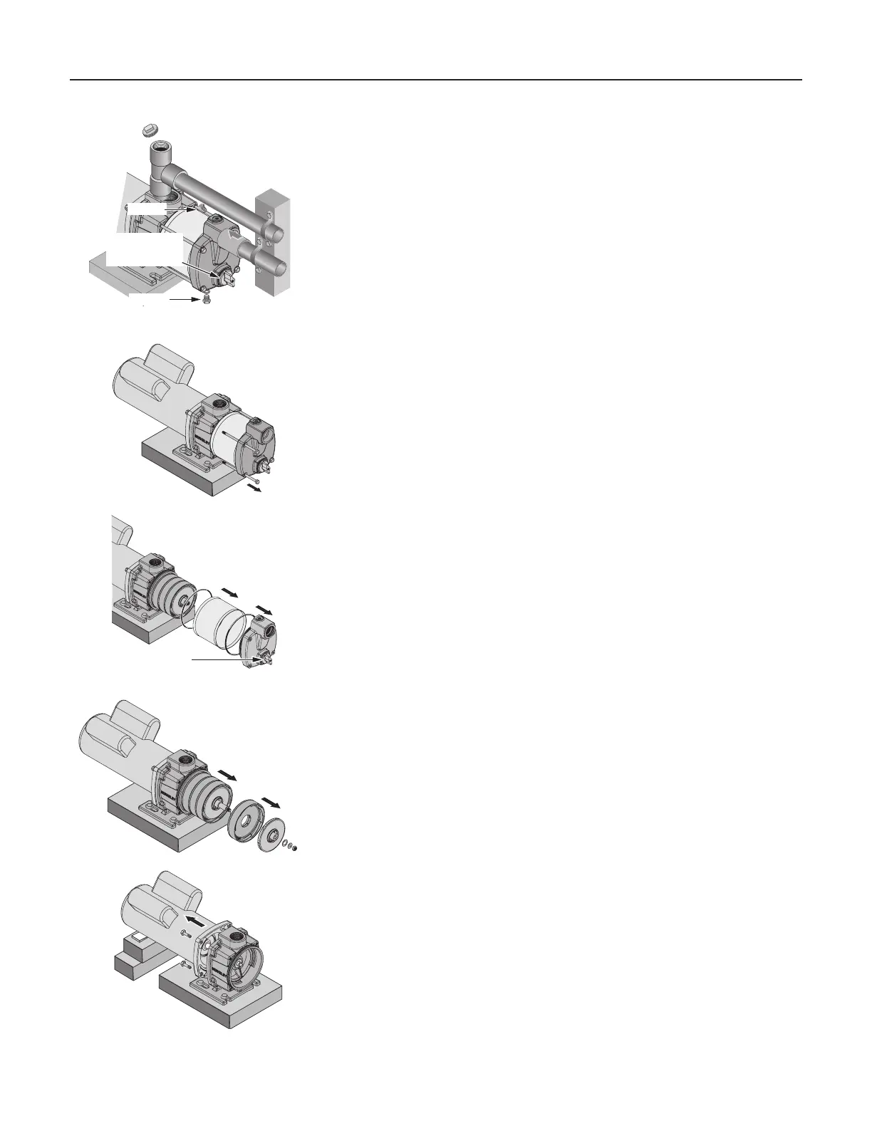
3. Remove the hex head drain plug (Key No. 17) from the suction body
and drain the pump.
4. Disconnect the suction line.
5. Remove four capscrews (Key No. 18) from the pump (see Figure 17).
6. Pull the pump suction body forward (see Figure 18). Remove the sleeve
(Key No. 9) by pulling it straight forward. Be careful not to damage the
O-rings on the bracket and suction body.
7. Remove the motor canopy, hold the motor shaft with a 7/16” open end
wrench, and remove the nut and two washers (Key Nos. 14, 13, 12)
from the end of the shaft. See Figure 19.
8. Slide the impellers and diffusers (Key Nos. 11, 10) off of the shaft
(Figure 19).
9. Slide the spacer (Key No. 7) off of the shaft, then pull the rotating half
of the seal (Key No. 6) forward on the shaft and remove it.
10.Block up the motor (so that the shaft will not take the weight of the
motor when you loosen the capscrews holding the motor to the brack-
et), remove four capscrews (Key No. 2), and slide the motor and shaft
back out of the bracket (see Figure 20).
NOTICE: To avoid springing the shaft, be sure that the shaft does not
take the weight of the motor as you remove it.
Figure 19
Figure 20
Figure 17
 Loading...