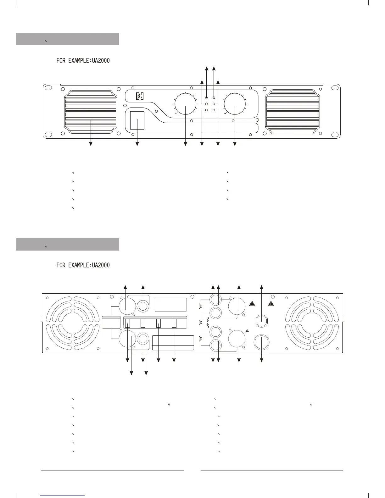
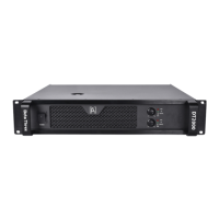
5 FRONT PANEL
UA SERIESUA SERIES
RR
PRO DESIGN
BETA THREE
UA2000
BRIDGE
PEAK
SIGNAL
00
-2-2
-4-4
-6-6
-8-8
-10-10
-12-12
-14-14
-16-16
-18-18
-20-20
-24-24
00
-2-2
-4-4
-6-6
-8-8
-10-10
-12-12
-14-14
-16-16
-18-18
-20-20
-24-24
CHBCHA
POWER
ON
OUTPUT ASSIGNMENT:
BRIDGE MONO OUTPUT:
CHA :
PIN1+ : SIGNAL
CHA:
PIN 1+ :
PIN 1 - :
PIN 2+ :
PIN 2 - :
CHA SIGNAL
CHA GND
CHB SIGNAL
CHB GND
CHB:
PIN 1+ :
PIN 1 - :
PIN 2+ :
PIN 2 - :
CHB SIGNAL
CHB GND
GND
PIN2+ :
1 2
3
4
5
6
7
8 9
6 REAR PANEL
13
1 air input port
2 signal indicator of channel A
3 overload indicator of channel A
4 bridge indicator of channel
5 overload indicator of channel B
1 signal input of channel A(XLR JACK)
2 signal input of channel A(1/4 mic jack)
3 switch of working modes
4 limiters
5 signal output of channel B(binding post)
6 signal output of channel A(binding post)
7 fuse
6 signal indicator of channel B
7 power switch
8 gain adjustment pots of channel A
9 gain adjustment pots of channel B
8 signal input of channel B(XLR plug)
9 signal input of channel B(1/4 mic jack)
10 filter switch
11 grounding switch
12 signal output of channel A(NL4 JACK)
13 signal output of channel B(NL4 JACK)
14 cable
CHA
BRIDGE IN
CHB
PIN1:
SIGNAL GND
PIN2:
SIGNAL +
PIN3:
SIGNAL -
BRIDGE
PARALLEL
STEREO
MODE
LF FILTER
GROUND
CLIPLIMITER
ON
OFF
50HZ
25HZ
ON
OFF
CHB OUTPUT
CHA OUTPUT
POWER
CABLE
FUSE
INPUT
-
B
+
-
A
+
-
+
5HZ
BRIDGE
1 2
3
4
5
6
7
8 9
10
11
12
13
14
CAUTION
RISK OF ELECTRIC SHOCK
DO NOT OPEN
!
Special design for big power£¡