A
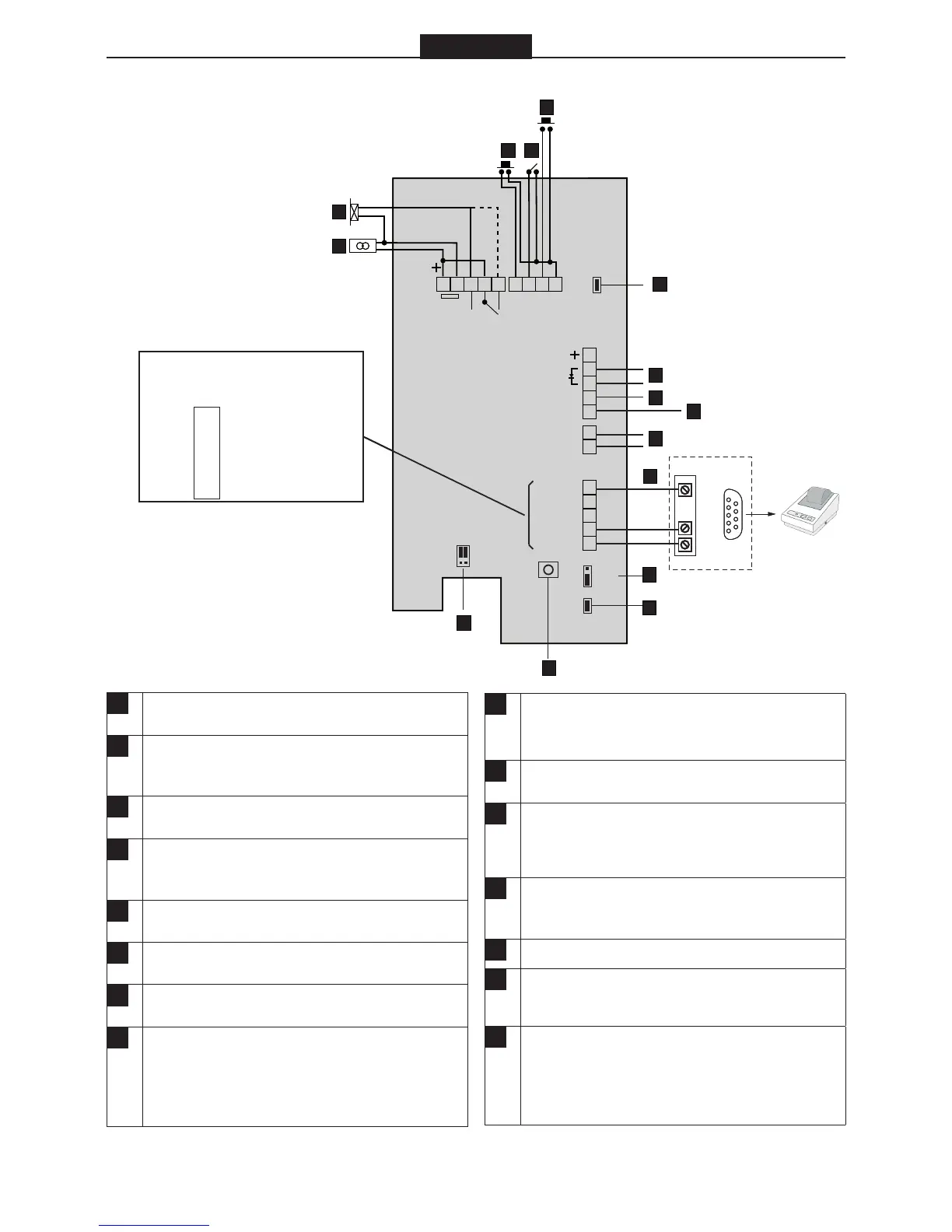
Electric locking device. Dashed line shows con-
nection to locks with power to lock operation.
B
Power in, terminal block nos. 1 and 2.
BC615Cotag/EM: 12 – 35 VDC.
BC615: 8 - 24 VAC or 10 – 35 VDC.
C
Exit request button. To operate, short terminal
nos. 6 and 9.
D
Input for door monitor contact. Link out by jumper
F if not used. The contact should be closed when
the door is closed.
E
Input for reader inhibit. To operate, short terminal
nos. 8 and 9. The red LED on the reader flashes.
F
Place jumper if door monitor contacts are not
used.
G
Alarm set input (red LED lit). Terminal no 11 “+”,
no 12 “–”.
H
Alert output. Use an E7 relay. Connect between
terminal nos. 13 and + (10). Activated when a door
is forced open or following door release + door
held warning time and when door contacts are not
closed.
I
Duress output. Used for activating an external
alarm. Use an E7 relay. Connect between terminal
nos. 14 and + (10).
J
Tamper switch. Normally closed when the housing
is closed.
K
Connection to printer. For connection to PC, see
the diagram. RS232 interface: 9 600 bps, no par-
ity, 8 bits, 1 start bit, 1 stop bit
L
If the card reader is used with Bewator Entro sys-
tem, attach jumper to N/W (network), otherwise to
S/A (standalone).
M
Remove jumper if backlighting is not required.
N
The SW1 push button. Used when erasing the
memory and setting a new password.
O
If the card reader is part of a Bewator Entro sys-
tem, place jumper on INT (attempts of tamper will
be displayed as messages on the PC’s screen),
otherwise to EXT. (Direct connection to external
alarm)
 Loading...