INSTALLATION MANUAL
Thank you for buying this product, our company is sure that you will be more
than satised with its performance.
This product is supplied with an “Instruction Manual” which should be read ca-
refully as it provides important information about safety, installation, operation
and maintenance.
This product complies with recognised technical standards and safety regula-
tions. We declare that it is in conformity with the following European Directives:
2004/108 EEC, 2006/95 EEC and subsequent amendments.
1) GENERAL OUTLINE
The ALTAIR-P control panel is suitable for swing gates. It is supplied by the manufac-
turer with standard functional settings. Any alteration must be set by means of the
incorporated display programmer or by means of universal palmtop programmer.
The Control unit completely supports the EELINK protocol.
Specications:
- management of two motors with electronic torque setting.
- Radio receiver: 433.92 MHz rolling-code or xed code
- Maximum numbers of radio control devices to be managed: 63
- Centralised controls with other controllers: presetting for serial protocol with
an external accessory.
3) CONTROL UNIT TECHNICAL SPECIFICATIONS
Power supply: ........................................................................................ 230V
~
±10% 50Hz*
No-load absorption from the mains: ................................................................... 0.2A max
Mains/low voltage insulation: ...........................................................> 2MOhm 500V
Dielectric strength: ........................................mains/low voltage 3750V~ for 1 minute
Motor output current: ................................................................................1.25A+1.25Amax
Motor relay commutation current: .................................................................................10A
Maximum power with 2 motors: ...................................................................300W+300W
Maximum power with 1 motor: ................................................................................. 300W
Blinker: .......................................................................................................................... 40W max
Gate-open warning light: ..............................................................................24V
~
3W max
Supply to accessories: ....................................................... 24V
~
(0.2A max absorption)
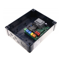
Degree of protection for box: ........................................................................................ IP 55
Dimensions: .............................................................................................................. see gure 1
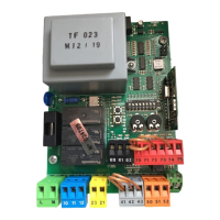
Fuses: .........................................................................................................................see gure 2
(*other voltages available on request)
4) TERMINAL BOARD CONNECTIONS (Fig.3)
WARNING - During wiring and installation operations, refer to the current
standards and to principles of good technical practice.
Wires powered at dierent voltages must be physically separated, or suitably
insulated with at least 1 mm extra insulation. The wires must be clamped by an
extra fastener near the terminals, for example by bands.
The capacitors must be inserted inside the control unit box and adequately
xed to it.
WARNING! For connection to the mains, use a multipolar cable with a
minimum of 3x1.5mm
2
cross section and complying with the previously
mentioned regulations. For example, if the cable is out side (in the open), it
has to be at least equal to H07RN-F, but if it is on the inside (or outside but
placed in a plastic cable cannel) it has to be or at least egual to H05VV-F
with section 3x1.5mm
2
.
TERMINAL DESCRIPTION
1 GND terminal (yellow/green earthing cable)
2 Single-phase mains supply (L)
3 Single-phase mains supply (N)
4-5-6 Connection to motor 1:
4 on 1 + Capacitor
5 common
6 on 2 + Capacitor
7-8-9 Connection to motor 2:
7 on 1 + Capacitor
8 common
6 on 2 + Capacitor
10-11
230V
~
output for blinker light (40W max)
13-14
24V
~
180mA max output – supply to photocells or other
devices
15-16
Output (N.O. contact (24V
~
/0.5A max)) for gate-open warning
light or, alternatively, 2nd radio channel (see paragraph 6
“conguration”).
17-18 STOP push (N.C.) input. If not used, leave the bridge connected.
17-19 PHOTOCELL (N.C.) input. If not used, leave the bridge connected
17-20 DIP START-OPEN= OFF:
START push (N.O.).
DIP START-OPEN= ON:
OPEN push (N.O.).
17-21 DIP PED-CLOSE= OFF:
PEDESTRIAN input (N.O.). Activation only takes place on motor
2 for the Pedestrian operation time, if the opening cycle has
started (not from pedestrian function), the pedestrian control
is considered as a START control.
DIP PED-CLOSE= ON:
CLOSE input (N.O.).
31-32 Antenna input for integrated radio-receiver board
(31: SIGNAL. 32: BRAID)
5) PROGRAMMING
The control panel provided with a microprocessor is supplied with function
parameters preset by the manufacturer, suitable for standard installations. The
predened parameters can be altered by means of either the incorporated display
universal palmtop programmer.
In the case where programming is carried out by means of
universal palmtop
programmer
, carefully read the instructions relating to
universal palmtop pro-
grammer
, and proceed in the following way.
Connect the universal palmtop programmer to the control unit through the
UNIFLAT accessory (See g. 4). Enter the “CONTROL UNITS” menu, and the “PA-
RAMETERS” submenu, then scroll the display screenfuls using the up/down arrows,
and set the numerical values of the parameters listed below.
For the function logics, refer to the “LOGIC” submenu.
In the case where programming is carried out by means of the incorporated
programmer, refer to Fig. A and B and to the “conguration” paragraph.
6 CONFIGURATION
The display programmer is used to set all the ALTAIR-P control panel functions.
The programmer is provided with three pushbuttons for menu scrolling and
function parameter congurations (Fig. 2):
+ menu scrolling/value increment key
- menu scrolling/value reduction key
OK Enter (conrm) key
The simultaneous pressure of the + and – keys is used to exit the active menu
and move to the preceding menu.
If the + and – keys are pressed simultaneously at the main menu level (parameters,
logics, radio, language, default), programming is exited and the display is switched
o (the END message is displayed).
The modications made are only set if the OK key is subsequently pressed.
When the OK key is pressed for the rst time, the programming mode is entered.
The following pieces of information appear on the display at rst:
- Control unit Software version
- Number of total manoeuvres carried out (the value is expressed in thousands,
therefore the display constantly shows 0000 during the rst thousand ma-
noeuvres)
- Number of manoeuvres carried out since the latest maintenance operation
(the value is expressed in thousands, therefore the display constantly shows
0000 during the rst thousand manoeuvres)
- Number of memorised radio control devices.
When the OK key is pressed during the initial presentation phase, the rst menu
(parameters) can be accessed directly.
Here follows a list of the main menus and the respective submenus available.
The predened parameter is shown between square brackets [ 0 ].
The writing appearing on the display is indicated between round brackets.
Refer to Figures A and B for the control unit conguration procedure.
6.1) PARAMETERS MENU
- Operation time (vork. t) [010.0s]
Set the numerical value of the operation time from 3 to 180 seconds.
- Pedestrian operation time (ped. t) [006.0s]
Set the numerical value of the control panel operation time from 3 to 90
seconds.
- Automatic Closing Time (TCA) [ 010.0s ]
Set the numerical value of the automatic closing time from 3 to 120 seconds.
WARNING: Check that the impact force value measured at
the points established by the EN 12445 standard is lower than that speci-
ed in the EN 12453 standard.
Incorrect sensitivity setting can cause injuries to persons or
animals, or damage to things.
- Opening delay time (open delay time) [ 001.0s ]
Set the opening delay time between 1 and 10 seconds.
- Closing delay time (cls delay time) [ 001.0s ]
Set the closing delay time between 1 and 60 seconds.
- Motor torque (mot torque) [ 050% ]
Set the numerical value of the motor torque between 1% and 99%.
14 - ALTAIR-P
D811506_04
 Loading...