INSTALLATION MANUAL
1) GENERAL OUTLINE
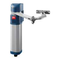
The BOTTICELLI 800 U system is suitable for motorising sectional doors (g. C),
protruding fully retracting spring-operated overhead doors (g. B) and counter-
weight overhead doors provided with an appropriate towing arm (g. D). The
overhead door must not be higher than 3 metres. Its easy installation allows fast
tting without needing the door to be modied. The irreversible gearmotor keeps
the door locked in the closing position.
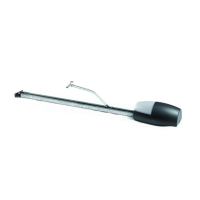
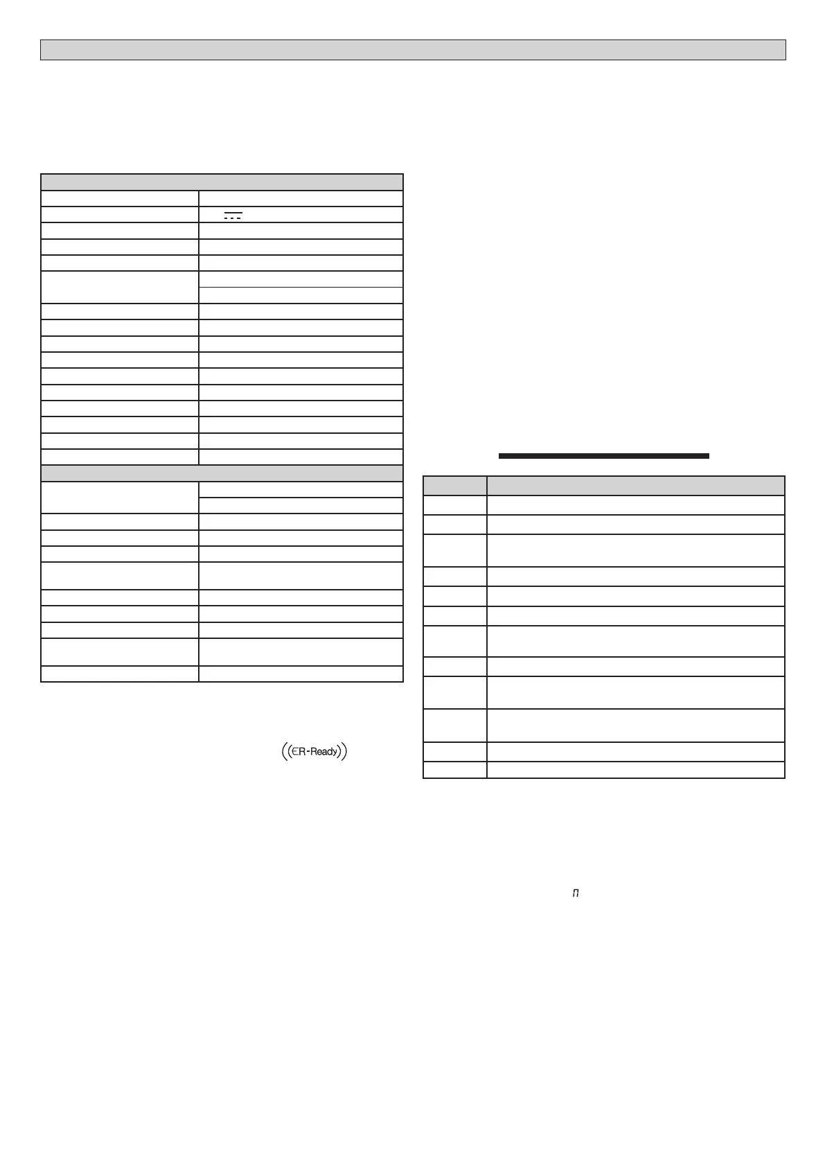
2) TECHNICAL SPECIFICATIONS
ATTUATORE
Power supply 230V ~±10%, 50/60Hz single-phase (*)
Motor voltage 24V
Max. power absorbed from mains 180W
Lubrication permanent grease
Towing and pushing force 800 N
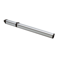
Working stroke
BINARIO L.=2900 working stroke=2400 mm (**)
BINARIO L.=3500 working stroke=3000 mm (***)
Average speed 5 m/min
Impact reaction integrated torque limiter on control panel
Manoeuvres in 24 hours 20
Limit switch Electronic with ENCODER
Courtesy light BFT model courtesy LED lamp
Working temperature -15°C / +60°C
Degree of protection IPX0
Motor head weight 5 kg
Noise level <70dB(A)
Dimensions see g.1
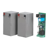
CONTROL PANEL
Supply to accessories
24V~ (180mA max)
24Vsafe (180mA max)
Torque limiter setting on closing and opening
Blinker connection 24V~ max 25W
Service light switching-on time 90s
Incorporated rolling-code radio
receiver
Frequency 433.92 MHz
Coding rolling-code algorithm
No. combinations 4 milliard
Antenna impedance 50 Ohm (RG58)
Max no. radio controls to be
memorised
63
Fuses see gure T
(*) Available in all mains voltages.
(**)By turning the motor head by 90° (Fig.N) the useful stroke will be 2580 mm.
(***)By turning the motor head by 90° (Fig.N) the useful stroke will be 3180 mm.
Usable transmitter versions:
All ROLLING CODE transmitters compatible with
3)
ELECTRICAL INSTALLATION SET-UP
Fig.A
Arrange for the connections of accessories and safety and control devices to
reach the motor unit, keeping the mains voltage connections clearly separate
from the extra low safety voltage connections (24V).
Proceed to connection following the indications given in the wiring diagram.
The cables for connecting the accessories must be protected by a raceway (g.
K ref. 5C1).
4) ACTUATOR INSTALLATION
4.1) Preliminary checks
• Check that the door is balanced.
• Check that the door slides smoothly along its entire travel.
• If the door has not been newly installed, check the wear condition of all its
components.
• Repair or replace faulty or worn parts.
• The automation reliability and safety are directly inuenced by the state of
the door structure.
• Before tting the motor, remove any superuous ropes or chains and disable
any unnecessary appliances.
4.2) FITTING
1) Remove the existing locking bolt from the cremone bolt of the door.
2) Fit the metal wall bracket to the track-holder bracket using the screws sup-
plied as standard (Fig.E1). The screws must not be tightened, so that the
bracket can be rotated.
3) In order for the track to be correctly xed, mark the mid-point of the door,
position the BIN onto the ceiling and mark the holes (Fig.F).
Make sure that the distance between the track and the door panel is com-
prised between 108 and 166 mm (see Fig.G). The table in Fig. H gives the
various combinations for fastening the bracket to the overhead door.
4) Drill the ceiling using a D.10 bit, with reference to the markings made previ-
ously, and insert the plugs. Fig. I.
5) Secure the track at the base, g.J (1-2), K (3-4-5).
6) With the help of an adequate support, lift the entire motor, screw the screws
onto the track-holding bracket without xing them to the door frame (Fig.
L1) or, if the height allows it, t the bracket to the masonry lintel by means
of plugs (Fig.L2).
7) Rest the motor onto the oor (taking care not to damage it) and x the
articulated bracket to the door frame or to the ceiling.
8) In the case where the motor is not directly xed to the ceiling, t the brack-
ets as shown in Fig.M, after marking and drilling the holes with reference to
the brackets.
9) In the case where the track is turned by 90° with respect to the motor head,
use the reference template in Fig. N1 to cut out the guard, keeping to the
measurements indicated. For track tting to the ceiling, see Fig.F (for tracks
tted lower, see Fig.E).
10) In the case where the track is made in two halves, see Fig.O; for the dierent
types of xing methods, see the previous gures.
11)
Release the carriage and x the anchoring brackets to the door panel (Fig.H).
The distance allowed between track and sectional door is 108 to 166 mm.
In case of greater distance, it is necessary to use the brackets and lower the
motor; in case of shorter distance, it is necessary to shorten the towing plate.
12) Stick the adhesive labels supplied next to the dangerous points (Fig. Q).
5) CHAIN TIGHTENER ADJUSTMENT (BOTTICELLI 800 U)
The operator supplied is already calibrated and inspected. Should the chain ten-
sion need to be adjusted, proceed as shown in g. R.
WARNING: the anti-tear rubber element must never be completely com-
pressed. Scrupulously check that the rubber does not become totally com-
pressed during operation.
6) MANUAL RELEASE (See USER GUIDE -FIG.1-).
----------------------------------------------------------
7) TERMINAL BOARD CONNECTIONS (FIG.T)
TERMINAL DESCRIPTION
JP2
transformer wiring
JP10
motor wiring
1-2
Antenna input for integrated radio-receiver board
(1: BRAID. 2: SIGNAL)
3-4
IC1 input (N.O.)
3-5
STOP input (N.C.) If not used, leave the jumper inserted.
3-6
SAFE1 input (N.C.) If not used, leave the jumper inserted.
3-7
FAULT1 input (N.O.)
Test input for safety devices connected to SAFE 1.
8-9
24 V~ output for blinking light (25 W max)
10-11
24V~ 180mA max output – power supply for photocells or
other devices.
12-13
24V~ Vsafe 180mA max output – power supply for checking
photocell transmitters.
14-15
AUX 3 (N.O.) congurable output
16-17 Ingresso IC2 (N.O.)
8) SAFETY DEVICES
Note: only use receiving safety devices with free changeover contact.
8.1) TESTED DEVICES Fig. T1
8.2) CONNECTION OF 1 PAIR OF NONTESTED PHOTOCELLS Fig. T2
9 CALLING UP MENUS: FIG. 1
9.1) PARAMETERS MENU PARA PARAMETERS TABLE “A”
9.2) LOGIC MENU LOGIC LOGIC TABLE “B”
9.3) RADIO MENU radio RADIO TABLE “C”
- IMPORTANT NOTE: THE FIRST TRANSMITTER MEMORIZED MUST BE
IDENTIFIED BY ATTACHING THE KEY LABEL (MASTER).
In the event of manual programming, the rst transmitter assigns the RECEIVER’S
KEY CODE: this code is required to subsequently clone the radio transmitters.
The Clonix built-in on-board receiver also has a number of important advanced features:
• Cloning of master transmitter (rolling code or xed code).
• Cloning to replace transmitters already entered in receiver.
• Transmitter database management.
• Receiver community management.
To use these advanced features, refer to the universal handheld programmer’s
instructions and to the general receiver programming guide.
9.4 MENU DEFAULT default
Restores the controller’s DEFAULT factory settings. Following this reset, you will
need to run the AUTOSET function again.
14 - BOTTICELLI 800 U
D812779 00100_08
 Loading...