Do you have a question about the BFT CAPRI and is the answer not in the manual?
Describes the CAPRI control unit for roller shutters, its versions, and compatibility with protocols.
Provides crucial safety guidelines for installation, use, and maintenance to prevent harm or damage.
Details motor power, radio frequency, control limits, dimensions, and protection degrees.
Guidance on unit placement, fastening, wiring preparation, and sensor positioning.
Specifies qualified technicians, required switches, cable types, and wiring separation rules.
Explains local and centralized wire control, master/slave setup, and zone addressing.
Configuring DIP switch 3 for hold-to-run controls, inhibiting serial and radio functions.
Details functions of radio control keys and manual receiver programming.
Covers radio programming, EElink protocol programming, and stored control limits.
Procedure for erasing all data from the board memory and restoring factory settings.
Information on board version, list description, manoeuvre counts, maintenance dates, and executors.
Interpreting the DL1 LED signals for diagnosing microprocessor faults or operational states.
Guidelines for regular maintenance by qualified personnel and proper disposal of materials.
Explanation of DIP-switch settings for anemometer, hold-to-run, loop type, and master/slave configuration.
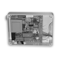
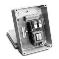
Illustrates the external dimensions of the control unit and internal component layout.
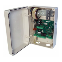
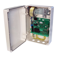
Shows the CAPRI control unit installed inside a shutter box for roller shutters.
Demonstrates the steps for marking, drilling, and mounting the control unit enclosure.
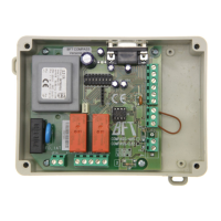
Detailed schematic showing internal component connections and DIP-switch functions.
Diagram illustrating the setup for a centralized wire control system with multiple units.
Shows the correct operation of push-buttons for opening and closing the automation.
Illustrates a centralized radio control system connecting multiple CAPRI units to motors.
Shows connections for UNIPRO programmer, UNIFLAT, UNIDA, and UNITRC accessories.
| Brand | BFT |
|---|---|
| Model | CAPRI |
| Category | Control Unit |
| Language | English |