EasyManua.ls Logo

BFT PERSEO-CBE User Manual

BFT PERSEO-CBE
24 pages
To Next Page IconTo Next Page
Page #1 background imageLoading...
Page #1 background image
,6758=,21,'¶862(',,167$//$=,21(
,167$//$7,21$1'86(5¶60$18$/
,16758&7,216'¶87,/,6$7,21(7'¶,167$//$7,21
,167$//$7,21681'*(%5$8&+6$1/(,781*
,16758&&,21(6'(862<'(,167$/$&,21
3(56(2&%(
3(56(2&%(
&(175$/(',&20$1'2
&21752/81,7
&(175$/('(&200$1'(
67(8(5=(175$/(
&(175$/'(0$1'2
Attenzione! Leggere attentamente le “Avvertenze all’interno! Caution! Read “Warnings inside carefully! Attention! Veuillez lire attentivement les Avertissements qui se trouvent à l’intérieur!
Achtun
g
! Bitte lesen Sie aufmerksam die „Hinweiseim Inneren!
¡
Atencn
¡
Leer atentamente las Advertencias en el interior! Let o
p
! Lees de “Waarschuwin
g
en aan de binnenkant zor
g
vuldi
g
!
D812189 00550_01 01-02-16

CAP
MOT
B
MOT
B
COM
COM
MOT
A
MOT
A
CAP
EV1
AC2
EV2
LAMP
AC2
SEM
RED
SEM
GRN
PRESS
1
COM
PRESS
2
AN.
IN
UPS
AUX
COM
SHIELD
ANT
START
PDM
OPEN
COM
CLOSE
FTC
STOP
COM
FCA
FCC
INPUTS
INPUTS
OUTPUTS HV OUTPUTS HV
OUT4
AUX
OUT5
2ndRX
24VAC1
24VAC2
OUT LED
24VAC2
OUT BUZZER
BRK +
BRK -
OUTPUTS LV
Question and Answer IconNeed help?

Do you have a question about the BFT PERSEO-CBE and is the answer not in the manual?

BFT PERSEO-CBE Specifications

General IconGeneral
BrandBFT
ModelPERSEO-CBE
CategoryControl Unit
LanguageEnglish

Summary

Introduction

Control Unit Overview and Components

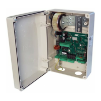
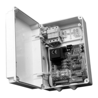
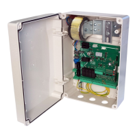
Details the main characteristics, display, buttons, and various terminal blocks of the control unit.

Technical Specifications

Power Supply and Motor Output

Specifies power supply voltage, motor output current, and operating ambient conditions.

Control Panel Dimensions

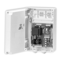
Provides the physical dimensions of the control panel unit.

Installation Safety

General Safety Precautions

Essential safety rules and prescriptions for electrical system installations.

Preliminary Operation

Bollard Selection Procedure

Steps for selecting the correct bollard type using buttons F and +/-.

Input and Output Functionality and Connections

J2 Power Terminal Block

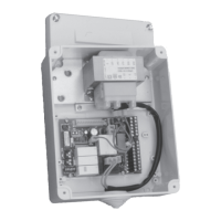
Details connections for the 230Vac power supply, including fuses and wiring.

J3A/J3B Power Terminal Block

Describes connections for motor, capacitor, and electrovalves for hydraulic bollards.

J4 Outputs/Accessories Terminal Block

Covers connections for electric brake, accessory power, lights, and buzzer outputs.

J5A/J5B Inputs Terminal Block

Explains connections for limit switches, safety inputs, photocells, and command inputs.

J6 Expansion Connector

Details the expansion connector for modules like TCP/IP or gateway.

J8 Programmer Connector for Receiver

Describes the connection for the programmer used with the radio receiver.

Display

Status Code Definitions

Explains the meaning of different status codes displayed on the unit.

Programming

Basic Functions and Navigation

Introduces programming access, levels, and basic navigation using buttons.

1st Level Programming

Configures operating logic (Hold-to-run, Semi-auto, Auto) and close input behavior.

2nd Level Programming

Configures maintenance requests, output settings, limit switch presence, and TERMON/UPS.

3rd Level Programming

Sets input/output polarity, pressure switch, and special PDM/frequency functions.

4th Level Programming

Configures communication protocols, MODBUS speed, and accesses historical error logs.

Radio Receiver

Receiver Technical Specifications

Lists technical specs like max transmitters, frequency, and code type.

Radio Channel Functionality

Describes how radio channels are selected and mapped to outputs.

Antenna Installation

Instructions for connecting the antenna to the receiver unit.

Manual Programming of Transmitters

Procedure for manually storing transmitters using PR1/PR2 and transmitter keys.

Self-Learning Transmitter Programming

Method for copying keys from an already stored transmitter to a new one.

Connections for Simultaneous Operation

Wiring for Multiple Bollard Control

Guides for connecting multiple bollards in parallel for simultaneous operation.

Troubleshooting Guide

Warnings

Installation and Usage Liabilities

Disclaimers regarding installation compliance, product use, and manufacturer liability.

Examples of Controlled Entries/Exits

Installation A: Controlled Entry or Exit

Scenario for one-way entry to a reserved area using a command.

Installation B: Automatic Entry or Exit

Configuration for automatic vehicle entry and exit without manual commands.

Installation C: Controlled Entry and Exit

Setup for entry and exit requiring commands in both directions.

Installation D: Controlled Entry and Automatic Exit

Scenario for controlled entry and automatic exit from a reserved area.

Error Handling

Fault and Event Table

Lists errors, their descriptions, and whether they cause blocking.

Related product manuals