.
6.5
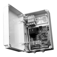
J6
EXPANSION CONNECTOR
6.6
J8
PROGRAMMER CONNECTOR
FOR RECEIVER
7. DISPLAY
At power-on the display shows the board type “&G+”, then the FW release X.Y.Z, then the type of bollard (see table on chapter cap. 5),
and nally the status or error code.
The status (initial ) or error code is always displayed except in programming menu or when a blocking error is present.
The status code is shown on the rst 2 digits.
On the third digit and dot, additional information is shown:
7.1 STATUS CODE
Display STATUS
UPS active, mains voltage failure
STOP signal active
"Termon" active
Photocell engaged
A standard cycle, without errors, is always 2
-> 3 when opening, 5 -> 6 when closing
: Idle
23
: Opening
: Opening limit switch reached
: Stop activated during opening
&/
: Closing
: Closing limit switch reached
: Stop activated during closing
)W
: Stop due to photocell triggering
: Opening after photocell triggering
: Pause after photocell triggering
2E
Hydraulic bollards only:
: Stop due to a detected obstacle
: Opening after a detected obstacle
: Pause after obstacle detection
7/
: Maximum working time in opening reached
: Maximum working time in closing reached
B EBA
RS 485
LINK BBU
B EBA
TCP/IP
GATEWAY
RS485
TCP/IP
MODULE