- 36 -
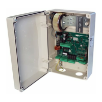
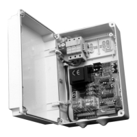
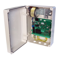
Control unit
EN
ENGLISH
11. TROUBLESHOOTING GUIDE
12. WARNINGS
The builder recommended to make an installation which has all the accessories necessary to ensure operation according to current provi-
sions, always using genuine devices.
This equipment must be installed and used in strict compliance with the manufacturer’s instructions. The manufacturer cannot be held
responsible for any damage deriving from improper or unreasonable installation and use.
The constructor disclaims all liability for any inaccuracies contained in this manual and reserves the right to make changes at any time wi-
thout any prior notice whatsoever.
10. CONNECTIONS FOR SIMULTANEOUS OPERATION (FIG. PAG. 2 and 3)
In the case of a malfunction, check that the correct bollard was selected (paragraph 5)
- Dual ashing of the cover lights. Indicates that scheduled maintenance is required. Check the parameters 6U, 1W, 1/
- Triple ashing of the cover lights and status 14 or 15 on the display at the end of the manoeuvre. Check the opening travel stop and the
pressure switch contact at the end of closing (hydraulic bollards only).
The control unit is used to operate up to a maximum of four bollards connected in parallel to thus obtain simultaneous operation with just
one control panel.
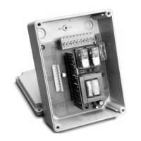
We recommend to use a junction box with adequate protection rating to complete the connections between two or more bollards. Fol-
lowing the table with indicated how to connect, serial or parallel, the common cables.
Refer to the speciÞ c bollard manual for identify the right wires.
*, *, +, +
+
', ', (, (,), ,,
&$, &%,R, R, 8, 8
MOTOR
Connect them in parallel respecting the polarity of the motors and joining the black cables, the brown cables and the blue cables
together. If present, joining the gray cables with the blue cable together.
CAPACITOR Connect in parallel the capacitor supplied with each bollard
ELECTRIC BRAKE NOT PRESENT NOT PRESENT
Connect the WHITE cables of the electric
brakes in parallel
LIGHT
Connect the YELLOW cables of the LED
lamps in parallel
Connect all YELLOW cables of the LED
lamps in parallel
Connect the YELLOW cables of the LED
lamps in parallel
HORN Connect the PINK cables of the horn contact in parallel
FCA
Connect the GREEN cables of the limit
switch in series.
Connect the GREEN cables of the limit
switch in parallel.
Connect the GREEN cables of the limit
switch in series.
FCC Connect the PINK cables of the limit switch in series, if present
PRESSURE SWITCH
PRES1
Connect the WHITE cables of the pressure
switch in parallel (used until 2012)
Connect the WHITE wires of the pressure
switch (used from 2013) in series
Connect the VIOLET cables of the pressu-
re switch in parallel
NOT PRESENT
PRESSURE SWITCH
ECD PRES2
Connect the GREEN cables of the ECD pressure switch in parallel, if present NOT PRESENT
BURGLAR
Connect the ORANGE cables of the bur-
glar device contact in series, if envisaged
Connect the GREEN/BROWN cables of
the burglar device contact in parallel, if
envisaged
Connect the ORANGE cables of the bur-
glar device contact in series, if envisaged
HEATING
ELEMENT
NOT PRESENT NOT PRESENT
Connect the RED cables of the heating
element in parallel, if envisaged
UNLOAD ELEC-
TROVALVE EV1
Connect the RED cables of the electrovalve element in parallel NOT PRESENT
UPLOAD ELEC-
TROVALVE EV2
NOT PRESENT
Connect the WHITE cables of the electro-
valve element in parallel
NOT PRESENT
ECD
ELECTROVALVE
NOT PRESENT
Connect the PINK cables of the electro-
valve element in parallel , if ECD present
NOT PRESENT