Do you have a question about the BFT POLLUCE 2M and is the answer not in the manual?
Defines gate behavior for closed, opening, opened, and closing states. Controls intermediate stops.
Defines gate behavior for closed, opening, opened, and closing states. Controls intermediate stops.
Function to halt gate operation until a restart command is given.
Configures SWO, SWC, and SCA functions via DIP3 switch for photocell and warning lights.
Enables automatic door closure upon photocell disengagement, bypassing TCA.
Prevents START commands during the opening phase of the gate.
Determines if the photocell is active only on closing or both opening/closing.
Enables or disables the automatic closing time function.
Selects between two-step (ON) or four-step (OFF) logic for gate operation.
This DIP switch is not used and should always be left in the OFF position.
Adjusts the automatic closing time for the gate, from 0 to 90 seconds.
Sets motor operating time to prevent damage if limit microswitches fail.
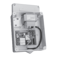
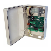
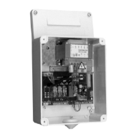
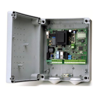
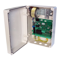
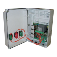
Details connections for power supply, start/stop buttons, photocells, and limit switches.
Covers radio receiver, courtesy light, and transformer connections for different voltage options.
| Brand | BFT |
|---|---|
| Model | POLLUCE 2M |
| Category | Control Unit |
| Language | English |