- 32 -
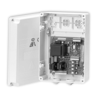
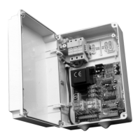
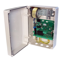
Control unit
EN
ENGLISH
8.4
3rd LEVEL
PROGRAMMING
The following table gives the 3rd level functions and the adjustable parameters.
= DEFAULT value set in factory.
= parameter value set during installation: should be lled if
DEFAULT value is modi ed.
&U
Deceleration torque (not avail-
able for hydraulic bollards)
67
Exiting the menu/saving Pressing the “F” key exits the programming menu and changes are saved
Description of level 2 parameters
· 6U: Request for maintenance
- : the request for maintenance is not active.
- : after the programmed cycles set by the counters QW and Q/, the programmed output is activated (see parameters R,R)
- : after the programmed cycles set by the counters QW and Q/, the programmed output is activated (see parameters R,R) and
the bollard lights ash twice.
· QW-Q/: Programming maintenance cycles in thousands and millions
These two parameters set the number of cycles after which a request for maintenance is signalled.
Thousands of cycles can be set with the QW parameter, millions of cycles with the Q/ parameter. Example: to set maintenance alarm
after 275 000 cycles, set Q/ to . and QW to .
·
)&: Closing limit switch presence.
This parameter must be set only for bollards with additional limit switch installed for closed-fully up position. After every default
operation it is set to for +and *$ bollards, for the others.
·
R=;R=: Assistance required
If con gured, the contact indicates that the electronic control unit detected an error in the automation and in particular, the failure
of the travel stop or the solenoid valve (hydraulic bollards only). The error is also signalled by the triple ashing of the cover lights, if
installed
· 7(: TERMON (integrated electronic motor heating system)
Should be activated ONLY when the ambient temperature where the bollard is installed drops below a minimum of 0°C for all the
day.
W( = , TERMON is disabled (default)
W( = , minimum heating
W( = , maximum heating
·
&U: Deceleration torque (electromechanical bollards only)
Sets the deceleration speed at the end of the closing manoeuvre.
The value of the deceleration speed at the end of opening is factory preset and cannot be modi ed.
Par. Function Settable data
3'
PDM dynamic input polarity
: input N.O.
: input N.C.
/7
Limit switch connection
: series (N.O. 2-wire sensors)
: parallel (N.C. 3-wire sensors)
33
Pressure switch polarity (for
hydraulic bollards only)
: N.O. (used until 2012)
: N.C. (used from 2013)
S(
ECD Pressure switch polarity
: N.O.
: N.C.
3$
Input AUX polarity
: N.O.
: N.C.
S
S
Output 4 polarity
Output 5 polarity
: N.O.
: N.C.
&3
Commands accepted during pause
time
: OFF
: ON