EasyManua.ls Logo

BFT Sirio TN1 User Manual

BFT Sirio TN1
8 pages
Go to English
To Next Page IconTo Next Page
Page #1 background imageLoading...
Page #1 background image
Via Lago di Vico, 44
36015 SCHIO (VICENZA)
Tel.naz. 0445696511
Tel.int. +39 0445696533
Fax 0445696522
INTERNET www.bft.it
E-MAIL sales@bft.it
ISTRUZIONI D'USO E DI INSTALLAZIONE
INSTALLATION AND USER'S MANUAL
INSTRUCTIONS D'UTILISATION ET D'INSTALLATION
INSTALLATIONS-UND GEBRAUCHSANLEITUNG
INSTRUCCIONES DE USO Y DE INSTALACION
CENTRALINA DI COMANDO
CONTROL UNIT
UNITÉ DE COMMANDE
STEUERUNG
CENTRAL DE MANDO
D811171 ver.05 24-02-99
SIRIO TN1
I
GB
F
D
E
8 027908 113566
Question and Answer IconNeed help?

Do you have a question about the BFT Sirio TN1 and is the answer not in the manual?

BFT Sirio TN1 Specifications

General IconGeneral
BrandBFT
ModelSirio TN1
CategoryControl Unit
LanguageEnglish

Summary

Control Unit Description and Operation

Operation Logic

Explains command impulses for gate movement (open, close, jam, reverse).

Functioning of Trimmers

Describes TW (running time) and TCA (stand-by time) trimmer adjustments.

Function of Bridges

Explains TCA, ALL, PH, BLI+TCA, BLI bridge configurations for gate behavior.

Functions of LEDs

Lists and explains the purpose of each LED indicator on the control unit.

Terminal Board Connections

JP4 230V~ Single-Phase

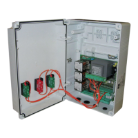
Details terminal board connections for 230V single-phase power and motor.

JP4 400V~ Three-Phase

Details terminal board connections for 400V three-phase power and motor.

JP3 Terminals

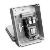
Explains the function of JP3 terminals for start, stop, limit switches, and photocells.

JP5 Terminals

Describes JP5 terminals for radio receiver connection and antenna input.

JP1 Mains Voltage Selection

Covers JP1 terminals for selecting mains voltage and emergency button.

JP6 Radio-Receiver Connector

Details the JP6 connector for the radio-receiver board.

Wiring Diagram and Connections

General Wiring Diagram

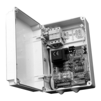
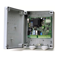
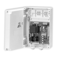
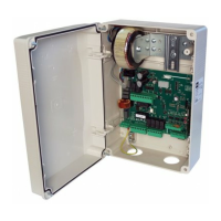
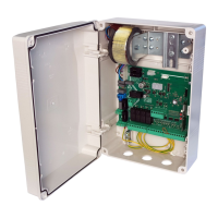
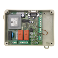
Provides a comprehensive overview of all electrical connections for the control unit.

Photocell and Safety Edge Connections

Details wiring for safety devices like photocells and pneumatic safety bars.

Motor and Auxiliary Device Connections

Explains connections for the motor, warning lights, and other accessories.

Related product manuals