OPERATOR AND RACK INSTALLATION
Technical Support: 1-877-995-8155
7
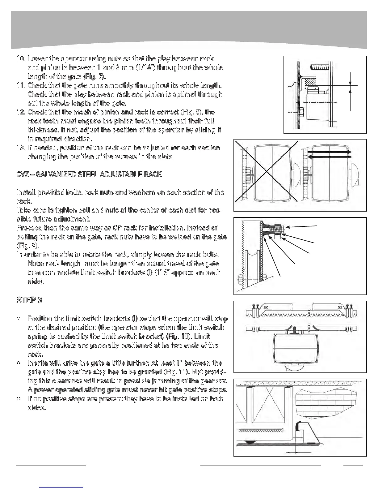
Lower the operator using nuts so that the play between rack 10.
and pinion is between 1 and 2 mm (1/16”) throughout the whole
length of the gate (Fig. 7).
Check that the gate runs smoothly throughout its whole length. 11.
Check that the play between rack and pinion is optimal through-
out the whole length of the gate.
Check that the mesh of pinion and rack is correct (Fig. 8), the 12.
rack teeth must engage the pinion teeth throughout their full
thickness. If not, adjust the position of the operator by sliding it
in required direction.
If needed, position of the rack can be adjusted for each section 13.
changing the position of the screws in the slots.
CVZ–GALVANIZEDSTEELADJUSTABLERACK
Install provided bolts, rack nuts and washers on each section of the
rack.
Take care to tighten bolt and nuts at the center of each slot for pos-
sible future adjustment.
Proceed then the same way as CP rack for installation. Instead of
bolting the rack on the gate, rack nuts have to be welded on the gate
(Fig. 9).
In order to be able to rotate the rack, simply loosen the rack bolts.
Note: rack length must be longer than actual travel of the gate
to accommodate limit switch brackets (I)(1’6”approx.oneach
side).
STEP 3
Position the limit switch brackets • (I) so that the operator will stop
at the desired position (the operator stops when the limit switch
spring is pushed by the limit switch bracket) (Fig. 10). Limit
switch brackets are generally positioned at he two ends of the
rack.
Inertia will drive the gate a little further. At least 1” between the •
gate and the positive stop has to be granted (Fig. 11). Not provid-
ingthisclearancewillresultinpossiblejammingofthegearbox.
A power operated sliding gate must never hit gate positive stops.
If no positive stops are present they have to be installed on both •
sides.
FIG. 7
1/16”
FIG. 8
NO !!
OK
FIG. 9
Welding
Rack spacer nut
Rack
Washer
Bolt
FIG. 10
FIG. 11
Min. 1”