DEIMOS Ver. 05 -
15
D811299_05
INSTALLATION MANUAL
ENGLISH
12) TERMINAL BOARD CONNECTIONS
First pass the appropriate electric cables through the raceways and fix the
various automation components to the chosen points, then connect them
following the directions and diagrams contained in the control unit instruction
manual.
Carry out phase, neutral and (compulsory) earth connections.
The mains power supply cables must be stripped as little as possible; the
power supply cable earth wire must be stripped for a greater length, in order
to reach the terminal purposely arranged in the box (fig. 15 ref. “A”).
The cables must be tied by additional fastening next to the terminals, by
means of clips for example.
All the operator wiring operations must be carried out by qualified personnel.
Operate the automation only after having connected and checked all the
safety devices.
A description of the terminals of MIZAR control unit installed on the actuator
is given below (fig. 16).
1-2 Single-phase power supply: (1=L) (2=N)
3-4-5 Motor connection (4 common, 3-5 operation and capacitor)
4-1 Blinker connection (mains voltage)
7-8 Open-Close push button, key selector (N.O.)
7-9 Stop push button (N.C.). If not used, leave jumped.
7-10 Photocell input or rubber skirt (N.C.). If not used, leave jumped.
Opening limit switch (N.C.). If not used, leave jumped.
Closing limit switch (N.C.). If not used, leave jumped.
13-14 24 V
180mA max output - power supply to photocells or other devices
15-16 Second radio channel output of twin-channel receiver board
Antenna input for radio receiver board (17 signal - 18 braid).
GND terminal
WARNING: If the opening direction is not correct, invert the motor
connections no. 3 and 5 and connections no. 11 and 12 of the opening and
closing limit switches.
13) MOTOR TORQUE SETTING (SAFETY CLUTCH)
WARNING: Check that the impact force value measured at the
points established by the EN 12445 standard is lower than that
specified in the EN 12453 standard.
The setting must be carried out according to whatever is provided for by the
current safety standards. For this purpose, the motor torque needs to be set
in the following way:
• Disconnect the mains power supply.
• Remove the screws securing the gearmotor guard.
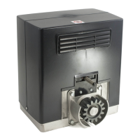
• Use the fixed key provided to lock the motor shaft (fig.17 - ref. “A”). Using
the release knob, screw the self-locking nut (fig.17 - ref. “D”) to increase
the torque, or slacken it to decrease the torque.
• Reconnect the power supply and, with the help of a torquemeter, check
that the motion stops at the mechanical resistance values set out by the
current standards.
• Put the protection guard back on the gearmotor and secure it with its
screws.
DANGER - The torque regulator must be calibrated before the
automation system is made to be operational.
14) MANUAL RELEASE
The manual or emergency release is to be activated when a gate must be
opened by hand, and in all cases where the automation system fails to
operate or operates incorrectly. To carry out the emergency manoeuvre,
proceed as follows:
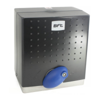
• Insert the standard key into its appropriate seat (fig. 18) and rotate it
anticlockwise (90°), then rotate the release knob clockwise along its
entire stroke. This way the pinion is made to idle, and therefore allows
the gate to be opened by hand.
Warning: Do not push the gate leaf hard, but rather help it along its
entire stroke.
• To reset motor-driven control, rotate the knob anticlockwise along its
entire stroke, and then rotate the standard key clockwise until it is held
tight. Keep the key in a safe place which is known to all the people
concerned.
In the case where the release knob is supplied with a personalised key (fig.
18), proceed as follows:
• Insert the personalised key into the lock, rotate the key anticlockwise by
90°.
• Hold the release knob and rotate it clockwise (fig. 18) until it stops.
This way the pinion is made to idle, and therefore allows the gate to be
opened by hand.
• Push the gate leaf by hand, helping it along its entire stroke.
The key cannot be taken out of the lock until the knob is brought back
to its initial position (motor-driven activation).
• To reset motor-driven control, rotate the knob anticlockwise along its
entire stroke, move the key back to its locking position; then take the key
out and keep it in a safe place which is known to all the people
concerned.
15) INSTALLATION CHECK
Before the automation device finally becomes operational, scrupulously
check the following conditions:
• Check that all the safety devices (limit microswitches, photocells, elec-
tric edges etc) operate correctly.
• Check that the rack and pinion are correctly meshed (minimum play 2mm).
• Check that the pushing force of the gate is within the limits provided for
by the current standards.
• Check that the opening and closing end-of-stroke runners are correctly
positioned and tightly secured.
• Check the starting and stopping operations using the manual control.
• Check the starting and stopping operations using the remote radio control.
• Check the normal or customised operation logic.
16) AUTOMATION DEVICE USE
Since the automation device can be controlled both remotely and in sight,
by means of a radio control device or a button, all the safety devices must
be frequently checked in order to ensure their perfect efficiency.
WARNING! In the event of any safety device malfunction, request
immediate assistance from qualified personnel.Children must be kept
at a safe distance from the automation operation area.
17) AUTOMATION CONTROL
The use of this control device allows the gate to be opened and closed
automatically. There are different types of controls (manual, radio control,
magnetic card access etc.) depending on the installation requirements and
characteristics. For the various control systems, see the relevant instructions.
The installer undertakes to instruct the user about correct
automation operation, also pointing out the actions to be taken in
case of emergency.
18) MAINTENANCE
WARNING! Before proceeding to any maintenance, disconnect the
mains power supply and, if the battery is fitted, one of its poles.
These are the check and maintenance operations to be carried out:
• Check the condition of lubrication of the metal racks once a year.
• Keep the sliding track always clean and free from debris.
• Occasionally clean the photocell optical elements.
• Have a qualified technician (installer) check the correct torque limit
setting.When any operational malfunction if found, and not resolved,
disconnect the mains power supply and request the assistance of a
qualified technician (installer). When the automation controller is out of
service, you can activate the manual release device (see paragraph on
“Emergency manoeuvre”) in order to set the pinion idling and therefore
allow the gate to be opened and closed by hand.
19) NOISE
The environmental noise produced by the gear-motor in normal operation
conditions is constant and does not exceed 70 dB (A).
21) SCRAPPING
Materials must be disposed of in conformity with the current regulations.
In case of scrapping, the automation devices do not entail any particular
risks or danger. In case of materials to be recycled, these should be sorted
out by type (electrical components, batteries, copper, aluminium, plastic etc.).
20) DISMANTLING
When the automation system is disassembled to be reassembled on
another site, proceed as follows:
• Disconnect the power supply and the entire external electrical installation.
• In the case where some of the components cannot be removed or are
damaged, they must be replaced.
21) MALFUNCTION: CAUSES and REMEDIES
21.1) The gate does not open. The motor does not turn.
1) Check that the photocells or the sensitive edges are not dirty, engaged,
or not aligned. Proceed accordingly.
2) Check that the electronic appliance is correctly supplied. Check the
 Loading...