Do you have a question about the BFT deimos ultra bt a 400 and is the answer not in the manual?
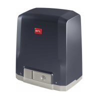
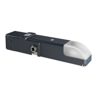
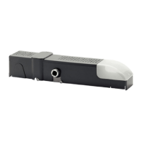
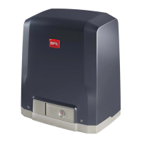
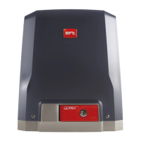
Introduction to the DEIMOS ULTRA BT series actuators and their key features.
Guidance on the purpose and scope of the installation and user manual.
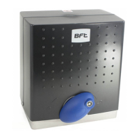
Visual instructions for performing emergency manual operation of the gate.
Guidelines for arranging tubes and cables for actuator installation.
Steps for preparing the installation site for motor mounting.
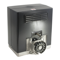
Procedures for mounting the motor and associated drive accessories.
Instructions on how to securely fasten the limit switch brackets.
Details on connecting optional boards, programmers, and display units.
Explanation of terminal board layout, power supplies, and safety device connections.
Overview of safety inputs, command inputs, motor, and power supply terminals.
Wiring diagram for photocells that are not checked periodically.
Wiring diagram for photocells that undergo periodic checks.
Guide to navigating and selecting parameters within the menu.
Guide to navigating and selecting logic settings within the menu.
Guide to navigating and selecting radio settings within the menu.
Options for preset parameter configurations like automatic or residential modes.
Configuration of operational logic like step-by-step, pre-alarm, and deadman modes.
Configuration for motor installation side (right or left).
Information on different rack types and their dimensions for installation.
Diagrams illustrating mounting procedures, rack centering, and component placement.
Details on the expansion board's capabilities and connections.
Instructions for using the universal palmtop programmer with the system.
Example application for gates with opposite leaves, including safety device connections.
Wiring diagram for connecting devices via the RS 485 link.
How to configure the gate's opening direction (right or left).
Step-by-step guide to restoring the control unit to its factory default settings.
Various wiring configurations for SAFE 1 input with photocells or bars.
Various wiring configurations for SAFE 2 input with photocells or bars.
Wiring diagrams for safety edge configurations, including 8K2 resistance.
Guide on how to access the main menu structures like Parameters, Logic, and Radio.
List and explanation of diagnostic codes and their corresponding error descriptions.
Overview of the actuator's features, capabilities, and protocols supported.
Detailed technical data including power, speed, torque, and environmental ratings.
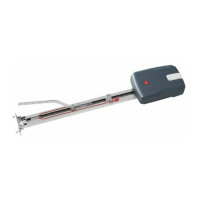
Step-by-step instructions for mechanical installation of the actuator and accessories.
Guidance on safety devices, menu access, and initial parameter setup.
Detailed table listing terminal functions, definitions, and descriptions.
Configuration options for auxiliary outputs, defining their functions.
Configuration options for command inputs, defining their functions.
Detailed configurations for safety inputs, including test and non-test modes.
Functions for resetting defaults, setting language, and performing autoset.
Steps for testing installation and accessing system statistics.
Configuration of password settings for programming access and security.
Parameters for automatic closing time and traffic light zone clearance.
Settings for slow-down distances and speeds during opening and closing.
Parameters for adjusting leaf force, opening speed, and closing speed.
Logic settings for automatic closing time and fast closing functions.
Logic for step-by-step movement and deadman operation modes.
Logic for managing pulses and the ice feature for low-temperature operation.
Detailed configurations for SAFE 1 and SAFE 2 safety inputs.
Configuration options for command inputs IC 1 and IC 2.
Configuration options for auxiliary outputs AUX 0 and AUX 3.
Settings for configuring the receiver for fixed-code transmitters.
Configuration of protection levels and password for menu access.
Settings for serial mode and network address for BFT network connections.
Configuration options for the input-output expansion board's first input (EXP11).
Configurations for expansion board inputs (EXP12) and outputs (EXPO I, EXPO2).
Functions for managing radio transmitters, including adding keys and erasing lists.
Configuration for traffic light pre-flashing and steady red light indicators.
| Power Supply | 230 V |
|---|---|
| Max Door Weight | 400 kg |
| Max Door Width | 6 m |
| Limit Switch Type | Electromechanical |
| Number of Remote Controls | 2 |
| Safety Features | Obstacle detection |
| Warranty | 2 years |
| Impact Reaction | D-Track |
| Locking | Mechanical |
| Release | Lever-operated release |
| Frequency of Use | Intensive |
| Motor Type | 24 V DC |
| Control Type | Remote control |