EasyManua.ls Logo

BFT BOTTICELLI SMART BT A 850 - User Manual

BFT BOTTICELLI SMART BT A 850
20 pages
Print Icon
To Next Page IconTo Next Page
Loading...
BOTTICELLI SMART BT A
850-1250
D813948 03A00_04 14-05-19
INSTALLATION AND USER’S MANUAL
AUTOMATION FOR OVERHEAD AND SECTIONAL GARAGE DOORS
Caution! Read “Warnings” inside carefully!
Question and Answer IconNeed help?

Do you have a question about the BFT BOTTICELLI SMART BT A 850 and is the answer not in the manual?

Summary

KIT COMPOSITION

Kit Components Overview

Details the components included in the kit for installation.

EQUIPMENT REQUIRED

Lists the tools required for the installation process.

MOTOR MOUNTING ON CEILING

Standard Ceiling Installation

Guide for mounting the motor unit on a standard ceiling height.

Higher Ceiling Installation (with extension)

Instructions for installing the motor on a higher ceiling using an extension.

DIMENSIONS AND RAIL ASSEMBLY

System Dimensions

Provides key measurements and specifications for the system.

Rail Assembly Procedure

Step-by-step guide for assembling the door's rail system.

BRACKET FIXING FOR CEILING AND WALL

Ceiling Rail Support Bracket Fixing

Instructions for securely attaching the rail support bracket to the ceiling.

Track Holding Bracket Wall Assembly

Details the process of assembling the track holding bracket on the wall.

Ceiling Rail Fixing with Brackets

Explains how to fix the ceiling rail using appropriate brackets.

TRACK AND HEAD ASSEMBLY

Track Assembly onto Holding Bracket

Guide for mounting the door track onto the previously assembled bracket.

Motor Head to Rail Connection

Instructions for connecting the motor head unit to the rail.

Rotated Head Installation Guidance

Specific guidance for installing the unit with a rotated motor head.

INITIAL SYSTEM START-UP

Start Up with Cover Closed

Steps for initial system startup with the cover in place.

ELECTRICAL WIRING AND INPUTS

SAFE1 and SAFE2 Input Configuration

Details configurations for safety inputs SAFE1 and SAFE2.

Command Input Configuration (IC1, IC2)

Defines configurations for command inputs IC1 and IC2.

Radio Channel Configuration Options

Outlines settings for radio channels.

ADVANCED START-UP PROCEDURE

System Startup and Configuration

Detailed procedure for system startup and initial configuration.

TRANSMITTER PROGRAMMING AND MANAGEMENT

Manual Transmitter Programming

Guide for programming transmitters manually.

Remote Transmitter Programming

Instructions for programming transmitters remotely.

Transmitter Cancellation Process

Steps to cancel or remove programmed transmitters.

ACCESS MENUS AND DIAGNOSTICS

Access Menus Overview

Overview of menu navigation and access levels.

PARAMETERS MENU DETAILS

Parameters Menu (PA-AN)

Details adjustable parameters for system configuration.

LOGIC MENU CONFIGURATION

Logic Menu (LOGIC)

Explains the logic settings for various functions.

MANUAL OPERATION AND MAINTENANCE

Manual Operation Guide

Instructions for operating the door manually.

Fuse Replacement Guide

Guide on how to replace the system's fuses.

System Accessories Description

Description of available accessories for the system.

Overview

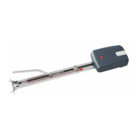
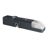
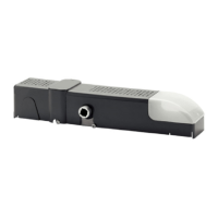
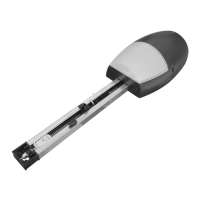
The BOTTICELLI SMART BT A 850-1250 is an automation system designed for overhead and sectional garage doors. It is suitable for motorizing sectional doors, fully retracting spring-operated overhead doors, and counterweight overhead doors equipped with an appropriate towing arm. The system can be used with overhead doors up to 3 meters high. Its design emphasizes easy installation, requiring no modifications to the existing door. A key safety feature is the irreversible gearmotor, which keeps the door locked in the closed position, enhancing security. The system is also "ER-Ready" and features U-LINK connectivity, indicating advanced integration capabilities and ease of use with other BFT systems.

Technical Specifications:

Electrical Data:

  • Power supply: 220-230V 50/60Hz
  • Max. power absorbed from mains:
    • BOTTICELLI SMART BT A 850: 200W
    • BOTTICELLI SMART BT A 1250: 250W
  • Fuses: 1.25 AT (refer to figure L-S in the manual for details)
  • Supply to accessories: 24V~ (180mA max), 24Vsafe (180mA max)
  • Blinker connection: 24V~ max 25W
  • Courtesy light: BFT model courtesy LED lamp 24V === 2W
  • Operating temperature: -20°C / +60°C

Mechanical Data:

  • Pulling and pushing force:
    • BOTTICELLI SMART BT A 850: 850N
    • BOTTICELLI SMART BT A 1250: 1250N
  • Leaf max.:
    • BOTTICELLI SMART BT A 850: 13m²
    • BOTTICELLI SMART BT A 250: 16m²
  • Working stroke:
    • TRACK L.=2900 working stroke=2300 mm
    • TRACK L.=3500 working stroke=2900 mm
  • Maximum speed:
    • BOTTICELLI SMART BT A 850: Belt track= 240 mm/s, Chain track= 210 mm/s
    • BOTTICELLI SMART BT A 1250: Chain track= 190 mm/s
  • Manoeuvres in 24 hours@ MAX+60°C:
    • BOTTICELLI SMART BT A 850: 50
    • BOTTICELLI SMART BT A 1250: 100
  • Manoeuvres in 1 hour@ MAX+50°C: 10
  • Typical installation of sectional doors at 20°C:
    • BOTTICELLI SMART BT A 850: mq 6,7 (100 consecutive manoeuvres)
    • BOTTICELLI SMART BTA 1250: mq 15,7 (50 consecutive manoeuvres)
  • Impact reaction: Integrated torque limiter on control panel
  • Limit switch: Electronic with ENCODER
  • Lubrication: Permanent grease
  • Degree of protection: IP20
  • Motor head weight: 5 kg
  • Noise level: <70dB(A)
  • Dimensions: See figure B in the manual

Incorporated Receiver Data:

  • Incorporated rolling-code radio receiver: Frequency 433.92 MHz
  • Coding: Rolling-code algorithm ((ER-Ready))
  • No. combinations: 4 billion
  • Max no. radio controls to be memorised: 63

Usage Features:

The system offers various operational modes and safety configurations. The "START UP WITH COVER CLOSED" procedure (Section I) guides the initial setup, including an autoset function. During autoset, obstacle detection is temporarily inactive, requiring the installer to monitor movements carefully. The system includes manual transmitter programming (Section N) for adding new remote controls and remote transmitter programming (Section O) for memorizing additional transmitters. A "TRANSMITTERS CANCELLATION" feature (Section P) allows for the removal of all memorized transmitters.

The "ACCESS MENUS" (Figure 2) provide detailed control over parameters and logic. These menus are protected by a password, with different protection levels (1, 2, 3, 4) depending on the desired security. The menus allow for scrolling up/down, confirming/switching on the display, and exiting.

Parameters Menu (Table A):

  • tca (Automatic Closing Time): Configurable from 0 to 180 seconds (default 40s), defining the waiting time before automatic closing.
  • ELIGHE (Lighting time of the courtesy light): From 30 to 300 seconds (default 90s), controlling the duration of the courtesy light.
  • QUE PUE EINE (Activation time of the timed output): From 1 to 240 seconds (default 10s), setting the activation length of the timed radio channel output.
  • oP.d 15t. SLoud (Slow-down distance during opening): From 7% to 99% (default 7%), defining the slow-down distance as a percentage of total travel. A complete uninterrupted opening-closing cycle is required after editing this parameter. Obstacle detection is inactive when the display reads "SET".
  • cL.d 15t. SLoud (Slow-down distance during closing): Similar to opening, from 7% to 99% (default 7%).
  • PACE IAL OPEN InG (Partial opening): From 1% to 99% (default 20%), setting the partial opening distance for pedestrian command.
  • OPForce (Leaf force during opening): From 1 to 99 (default 75), representing the percentage of force delivered before an obstacle alarm. This parameter is automatically set by the autoset function and directly affects impact force.
  • CLS.Force (Leaf force during closing): Similar to opening, from 1 to 99 (default 75).
  • OP SPEED (Opening speed): From 25% to 99% (default 99%), defining the maximum opening speed.
  • CL SPEED (Closing speed): From 25% to 99% (default 45%), defining the maximum closing speed.
  • PAINEE-nancE (Programming number of operations for maintenance threshold): From 0 to 250 (default 0), setting the number of operations after which maintenance is reported on the AUX output.

Logic Menu (Table B):

  • tca (Automatic Closing Time): Can be disabled (0) or enabled (1) to switch automatic closing on.
  • SEEP-69-SEEP Pou (Step-by-step movement): Configures inputs (Start E, Start I, Ped) for 4-step (0) or 3-step (1) logic.
  • Sυ Γου (Movement on endstop): Logic not active (0) or activates movement reversing when stopping on endstop (1).
  • PrE-ALAM (Pre-alarm): Flashing light comes on at the same time as motor start (0) or 3 seconds before (1).
  • IbL OPEN (Block pulses during opening): Pulse from inputs has effect during opening (0) or no effect (1).

Radio Menu (Table C):

  • Add 1ch, Add 2ch, Add 3ch, Add 4ch: Associate desired keys with radio channel commands.
  • ErASE 64 (Erase List): Erases all memorized transmitters.
  • ErASE I (Eliminates individual radio control): Removes a specific radio control.
  • cod H (Read receiver code): Displays receiver code for cloning transmitters.

Safety Input Configuration:

The system supports various safety devices, including photocells (Phot), safety edges (Bar), and 8k2 resistive edges. Configurations for SAFE 1 and SAFE 2 inputs (Table B) allow for different test modes (tested, active during opening only, active during closing only) and inversion active modes. The manual emphasizes checking impact force according to EN 12445 and EN 12453 standards and installing anti-crush safety devices where necessary.

Maintenance Features:

The manual outlines preliminary checks crucial for proper installation and long-term operation:

  • Door balance: Ensure the door is balanced.
  • Smooth travel: Check that the door slides smoothly along its entire travel.
  • Component wear: If the door is not newly installed, check the wear condition of all its components.
  • Faulty parts: Repair or replace any faulty or worn parts.
  • Automation reliability: The reliability and safety of the automation are directly influenced by the state of the door structure.
  • Obstruction removal: Before fitting the motor, remove any superfluous ropes or chains and disable any unnecessary appliances.

The system also includes a fuse replacement procedure (Section S) for easy maintenance. The "PAINEE-nancE" parameter allows setting a threshold for maintenance alerts, indicating when service is required.

For installations requiring work at heights greater than 2 meters, the manual mandates the use of higher safety level equipment such as scaffolding or rolling towers, with a reminder to check local legislation for activities outside Italy.

BFT BOTTICELLI SMART BT A 850 Specifications

General IconGeneral
BrandBFT
ModelBOTTICELLI SMART BT A 850
CategoryGarage Door Opener
LanguageEnglish

Related product manuals