IP 55
32
Ø 5
3,9
32
Ø5
22
19
22
24
36
19
22
24
1-Photocell TX
1-Photocell RX
1-Motor 1
1-Motor 2
230V mains
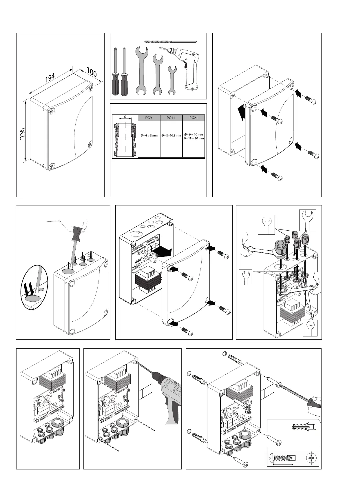
CONTROL PANEL INSTALLATION
DIMENSIONS
1� Close the control panel lid�
3� Open the control panel lid�
6� Drill the four holes shown�
5� Turn the control panel
upside down
7� Insert the Fisher dowels and x with
the screws as shown in the gure�
4�
Insert and x the cable glands�
2� Open the 5 holes shown by the arrows
using a pin remover�
WARNING:
PRESS (NOT TOO
HARD ON THE EDGE
AS SHOWN) to avoid
damaging the board
inside!!
TABLE OF CABLE OUTSIDE Ø
The table is only valid for the cable gland kit
supplied by the Company�
FABER BT - FABER L BT KIT - 43
D812458 10550_01