ON ON
OFF OFF
5
4
3
2
1
RX
2
1
TX
13
14
15
16 17
18
19
20 21
22
23
24
25
26
27 28
3
4
5
6 7
8
9
10
X
*
1 2 3 4 5 6 7 8 9 10
Y #
F2 4 AT
F1 1.25 AT
(220-230V)
F1 2.5 AT (120V)
S4
T1 T2 T3
T4
PWR ON
FLT2
FLT1
PHOT
STOP
OPEN
START
SW02
SW01
SWC2
SWC1
BAR
10
11
14 15
20
21
28 29
40
41
42
43
44
45 50
51
52
60 61
62
70
71
72
73
74 75
JP5 JP2
JP4
1 2 3 4
ON
5 6 7 8 9 10
1 2 3 4
ON
5 6 7 8 9 10
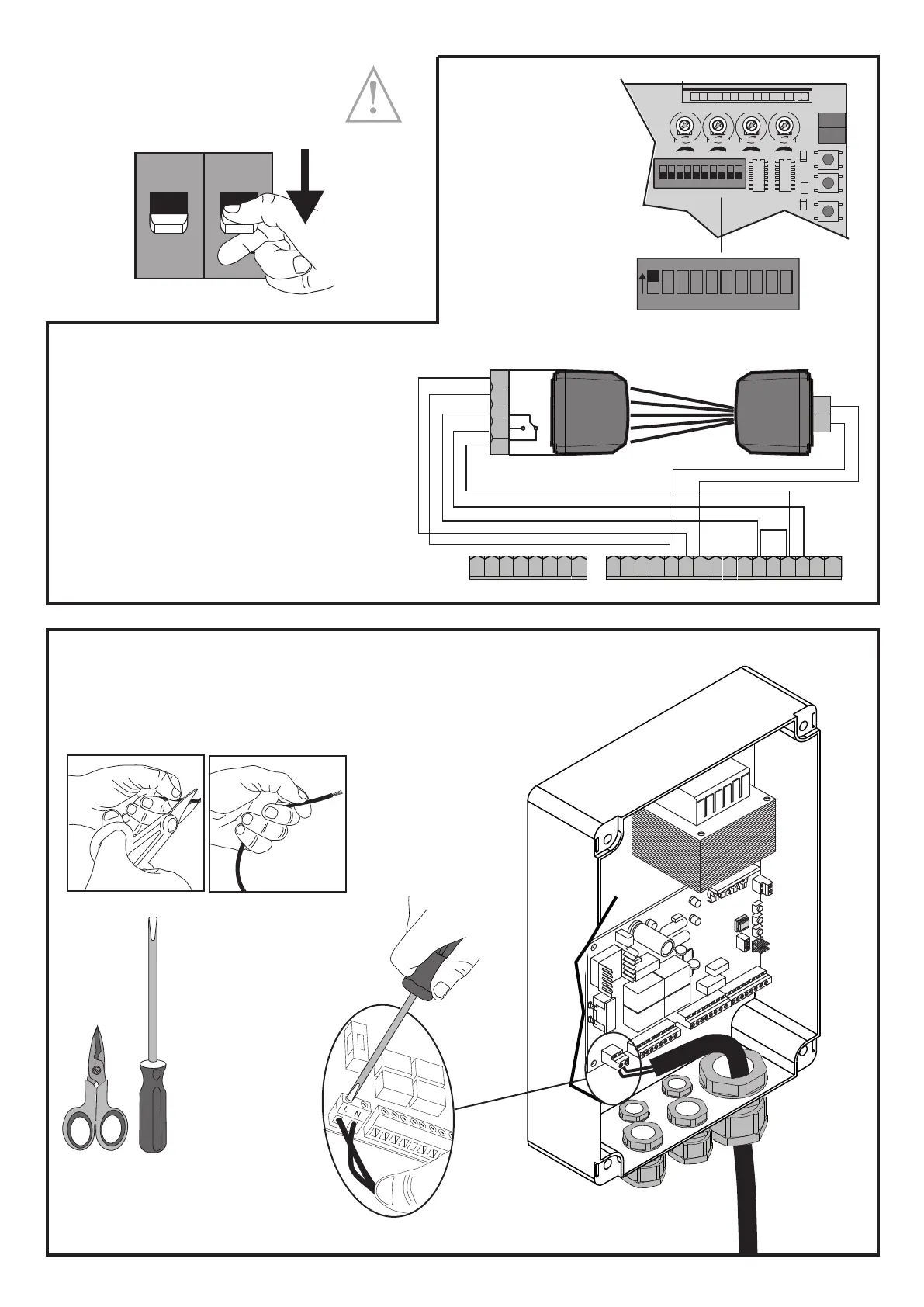
QUICK START
Warning: cut the power o
before any operation!!!!
Connect the PHASE (L) and NEUTRAL (N) wires
MAINS CONNECTIONS
PHOTOCELL CONNECTIONS
If the gate is installed in a public area or if the TCA is included
(automatic closing time), photocells must be installed�
To improve user safety, their installation is recommended
anyway�
* remove the factory jumper before making
the connection
FABER BT - FABER L BT KIT - 49
D812458 10550_01