2) GENERAL OUTLINE
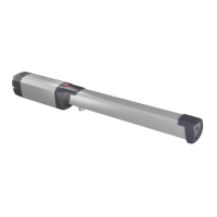
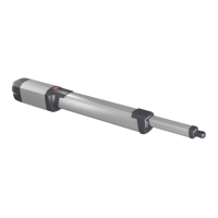
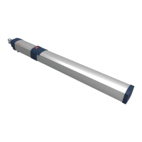
This Low-voltage controller (24V) is suitable for residential use and has been
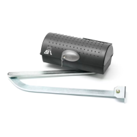
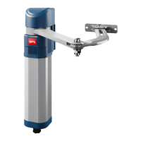
designed for swing gates with particularly large gate posts. The drive arm, built
with a special anti-shearing shape, allows the leaves to be moved when the
controller is considerably out of place with respect to the fulcrum of the leaves.
The non-reversible electro-mechanical gearmotor maintains the stop during
closing and opening.
The release knob with personalised key, tted outside each operator, makes
manual manoeuvre extremely easy.
WARNING! The installation, the maintenance and the repair should be done by respon-
sible and qualied persons with an updated knowledge of the current safety standards.
It’s strictly forbidden to service the automation when the power is on.
ATTENTION! The IGEA-BT model controller is not equipped with mechanical
torque adjustment. It is compulsory to use a control panel of the same manu-
facturer, in compliance with the basic safety requirements of directives 2006/95/
CEE, 2004/108/CEE, 2006/42/CEE equipped with appropriate electric adjusment
of the torque.
Installation must be carried out using the safety devices and controls prescribed
by the EN 12978 Standard.
3) TECHNICAL SPECIFICATIONS
Motor: ..............................................................................................................24V
1500 min
-1
Power: ....................................................................................................................................... 40W
Insulation class: ............................................................................................................................F
Lubrication: ................................................................................................. Permanent grease
Reduction radio: ................................................................................................................1: 812
Output shaft revolutions: ................................................................................1.8 min
-1
MAX
90° opening time: ..................................................................................................................15s
Torque supplied: ............................................................................................................ 300 Nm
Weight and max leaf length: .............................2000N (~200kg) for 2.5m leaf length
2500N (~250kg) for 2m leaf length
Impact reaction: ............................ Integrated torque limiter on LIBRA control panel
Motion drive: ...............................................................................................................Lever arm
Stop: ............................................................................ Incorporated electric limit switches
Manual manoeuvre: ..............................................Release knob with personalised key
Number of manoeuvres in 24h: ....................................................................................... 100
Environmental conditions: ................................................................................ -15 to +60°C
Degree of protection:.........................................................................................................IP 44
Operator weight: ................................................................................................160N (~16kg)
Dimensions: ...................................................................................................................See g. 1
Observe the safety distances as prescribed by the Standard in force.
4) OPERATOR INSTALLATION
WARNING! Refer to Fig.A for CORRECT installation.
4.1) Preliminary checks
Check that:
• Thegatestructureissucientlysturdyandrigid.
The xing position must be worked out according to the leaf structure. In any
case, the manoeuvring arm must push against a reinforced leaf point (g. 2).
• Theleavescanbemovedmanuallyalongtheirentirestroke.
If the gate has not been installed recently, check the wear condition of all its
components. Repair or replace defective and worn parts.
Operator reliability and safety are directly aected by the condition of the
gate structure.
4.2) Fitting of the manual release knob
• Withreferencetog.9,positionreleaseknob“A”onange“B”prettedon
the cover.
• Insertadaptingring“C”inthebushwithreleasetooth“D”.
WARNING: Depending on the operator installation position (right or left
side), insert ring “C” and position bush “D” as shown in g. 9.
• Insertspacewasher“E”andthenshimmingthrustbearing“F”intobush”D”
on the release tooth side.
• Secureeverything,usingappropriateself-tappingscrew“G”insidetheoperator
cover, checking the correct positioning of ring “C” and bush “D”.
• Closetheoperatorcover,usingtheappropriatescrewssupplied.
WARNING: The release tooth on bush “D” must be inserted in the release
lever as shown in g. 9b. Otherwise, the emergency manoeuvre cannot
be carried out.
Insertion is made easy by turning knob “A” to the side opposite to that for
manual release (clockwise in the case of a left-hand leaf, anticlockwise in
the case of a right-hand leaf) and locking it in such position by means of the
appropriate key.
Check that bush “D” is placed horizontally (g. 9b) and close the cover by po-
sitioning its front side (the one with the release knob) as indicated in g. 9c.
• Beforeconnectingtheoperatortothepowersupply,manuallycheckthat
the release knob operates correctly.
5) FIXING OF SUPPORTING PLATE (Fig.2)
The controller is supplied complete with anchoring bracket and lever arm.
Once the reinforcement point of the leaf has been identied with the gate closed,
draw an imaginary horizontal line from the centre of the reinforcement point
to the gate post (g.2). Position the anchoring bracket according to the values
given in g. 2 for openings of up to 90° or in g.3 for openings greater than 90°
up to a maximum of 125°.
Thebracketxingpositionmustbeatandparalleltotheleaf.Usescrewsor
expansion bolts which are suited to the type of gate post. If the surface of the
gate post is not regular, use expansion bolts with studs so that the parallel plate
of the leaf can be adjusted (g.4).
• Fastenthegearmotortothegatepostusingthe4screws,pointingthege-
armotor to the left or the right (g.5).
• Assembletheleverarmasshowning.6.
DX= assembly on the right leaf
SX= assemby on the left leaf
Choose the most suitable position of ‘F’ bracket for the fastening to the leaf.
• Insertthesquareoftherstleverintheoutputshaftofthegearmotorand
fasten it (g.7).
• Releasetheoperatorbyturningthereleaseknobtoalloweasymovementof
the arm (see paragraph on “EMERGENCY MANOEUVRE”).
• Thecorrectpositionforthecontrollerarmisshowning.8.
The leaf xing point can be identied by positioning the arm so that it is in
accordance with the distance shown in g.8.
• Fixtheangulartowingbar“F”totheleafbyweldingorusingscrews.
• Withthecontrollerreleased,checkthecorrectmovementofthearm.
• Repeatthesameoperationfortheotherleaf,ifinstalled.
6) ELECTRICAL INSTALLATION SET-UP
Arrange the electrical installation as shown in g.10.
The power supply connections must be kept separate from the auxiliary con-
nections (photocells, sensitive edge, etc.). Fig.10 shows the cross-section and
the number of connections.
WARNING! For connection to the mains, use a multipolar cable with a
minimum of 4x1.5mm
2
cross section and complying with the previously
mentioned regulations. For example, if the cable is out side (in the open), it
has to be at least equal to H07RN-F, but if it is on the inside (or outside but
placed in a plastic cable cannel) it has to be or at least egual to H05VV-F
with section 4x1.5mm
2
.
In g.11 you will nd the junction-box of the operator and the position of the
cable holder which should be xed with an adequate tightening of the bolt. In
case the motor tours in the opposite side, you should invert the running buckle
“M” of the operator. Refer to the relevant instruction manual for connection of
the control panel. Inside the operator the cable must be kept far from those parts
which can be hot.
7) LIMIT-SWITCH SETTING
• Positionthelimit-switchreferencecams“R-FC1”and“R-FC2”asshowning.
12, without tightening the xing screws.
• Identifytheopeningandclosinglimitswitches(FC1andFC2)keepinginmind
that:
In the left-hand operator (g. 13):
FC1 corresponds to the OPENING limit switch
FC2 corresponds to the CLOSING limit switch
In the right-hand operator (g. 14):
FC1 corresponds to the CLOSING limit switch
FC2 corresponds to the OPENING limit switch
• Whenthegateisfullyclosedoropened,rotatethecorrespondingcamuntil
you perceive the click of the limit microswitch concerned, and lock it in po-
sition by tightening the appropriate screws as shown in g. 12.
• Checkthatthelimitswitchesintervenecorrectly,initiatingafewcomplete
motor-driven opening and closing cycles.
• Fitthecoverontheoperator.
• Ifthecontrolpanelisprovidedwithoperation-timesetting,thismustbeset
to a value slightly greater than that needed for limit-switch intervention.
• Control the operator through the control board Libra.
8) ADJUSTMENT OF LEAF PHASE DISPLACEMENT
In case of gates with two leaves, the control panel should include a delay setting
function on closing of the second leaf to guarantee a correct closing manoeuvre.
For the wiring of the motor which should close with a slight delay, refer to the
instructions for the control panel installed.
9) MOTOR TORQUE ADJUSTMENT
WARNING: Check that the impact force value measured at the points
established by the EN 12445 standard is lower than that specied in
the EN 12453 standard.
The adjustment of the motor torque (anti-squashing) is performed on the
control panel. See control unit instruction manual.
The adjustment should be set for the minimum force required to carry out the
opening and closing strokes completely observing, however, the limits of the
10 - IGEA-BT
 Loading...