INSTALLATION MANUAL
12 - LUX BT 2B - LUX G BT 2B
D811702 00100_01
2) GENERAL INFORMATION
Strong, compact hydraulic piston, available in various versions depending on
TQFDJöD OFFETBOEöFMEPGVTF5IFSF BSFNPEFMTGFBUVSJOH IZESBVMJDMPDLJOH
BOEOPOMPDLJOHSFWFSTJCMFNPEFMTUIBUOFFEBTPMFOPJEMPDLUPLFFQUIFNJO
position.
0QFSBUJOHGPSDFJTBEKVTUFEXJUIFYUSFNFQSFDJTJPOCZNFBOTPGUIFDPOUSPMVOJUT
electronic control. Operation at the end of travel is adjusted electronically in the
control panel.
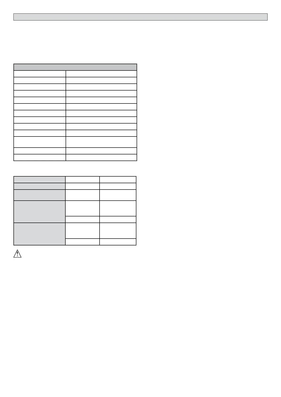
3) TECHNICAL SPECIFICATIONS
1PXFSTVQQMZ 24V
.BYQPXFSJOQVU 300W
.BYQSFTTVSF 30 bar
Pump delivery rate 1,2 l/min.
Operating force 3000 N
Pulling force 2600 N
Ambient temperature range - 20°C to 60°C
Impact reaction FMFDUSPOJDDMVUDIXJUIDPOUSPMQBOFM
Manual operation release key
Protection rating IP 55
Actuator weight LUX BT 2B: 8,4 kg
LUX G BT 2B: 9,3 kg
Overall dimensions Fig. Q
Oil *ESPMVY8JOUFS
4QFDJBMTVQQMZWPMUBHFTUPPSEFS
Table 1:
MOD. LUX BT 2B LUX G BT 2B
LOCKING TYPE Hydraulic Hydraulic
ACTUAL TRAVEL TIME 14 sec. 2 0 sec.
LEAF MAX.
(m)
(Kg)
2 5--2
300 300/800
TRAVEL mm
usable
total
270 392
290 412
WARNING: With leaves over 3 metres long, the solenoid lock must be
used and locking devices must be opened (Fig. M Ref. 2)
4) TUBE ARRANGEMENT Fig. A
5) PILLAR FASTENINGS INSTALLATION DISTANCES Fig. B
6) INSTALLATION DIAGRAM Fig. C
P rear bracket fastening to pillar
F front fork fastening leaf
a-b distances for determining bracket “P” fastening point
$WBMVFPGGBTUFOJOHDFOUSFUPDFOUSFEJTUBODFTFFFig. Q
D gate length
9EJTUBODFGSPNHBUFBYJTUPDPSOFSPGQJMMBS
;WBMVFBMXBZTHSFBUFSUIBONNC9
LH NBYXFJHIUPGMFBGTable 1
α° leaf opening angle
7) FASTENING OF FITTINGS TO PILLAR Fig. D
8) POWER CABLE Fig. E
9) ATTACHING MOTOR TO FASTENING ON PILLAR Fig. F
10) MAXIMUM TILT Fig. G
11) ENCODER ROD ASSEMBLY Fig. H
12) CORRECT INSTALLATION Fig. I
$PSSFDUJOTUBMMBUJPOFOUBJMTNBJOUBJOJOHBSPETUSPLFNBSHJOPGBQQSPYNN
to avoid possible trouble with operation.
13) FASTENING OF FITTINGS TO LEAF Fig. L
14) LOCKING SETTING Fig. M
15) COVER POSITIONING Fig. N
16) ELEASE COVER FASTENING Fig. O
17) MAIN PARTS OF AUTOMATED SYSTEM Fig. P
.7QFSNBOFOUNBHOFUNPUPS
1-PCFQVNQ
%$POUSPMWBMWFBTTFNCMZ
$$ZMJOEFSXJUIQJTUPO
&-JOFBS&ODPEFS
$PNQPOFOUTQSPWJEFEöUUJOHTBUUBDIFEUPQJMMBSBOEHBUFSFMFBTFLFZJOTUSVD-
tion manual.
18) TIPS FOR SPECIAL INSTALLATIONS
With the leaf fully open, create a recess to accommodate the operator.
Fig. R gives the minimum dimensions of the recess for the various LUX BT 2B -
LUX G BT 2B models.
If distance “b” is greater than the values given in the installation tables:
- create a recess in the pillar Fig.S
- move the leaf so that it is ush with the pillar Fig.T.
19) LEAF STOPS AT GROUND LEVEL
For the actuator to work properly, it is advisable to use stops “F” to stop the leaves
both when they are open and closed, as illustrated in Fig.U.
The leaf stops must prevent the actuator rod from reaching the end of its tra-
vel.
20) TOPPING UP OIL Fig. V.
An oil change is recommended every 5 years.
21) MANUAL OPENING (See USER GUIDE -FIG.1-).
 Loading...