14 - MIME AC
INSTALLATION MANUAL
INSTALLATION MANUAL
MANUALE PER L’INSTALLAZIONE
11.2) MODALITA LUCE (Fig. E)
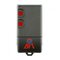
- MEMORIZZAZIONE RADIOCOMANDO SU USCITA 1 (Fig. F)
- MEMORIZZAZIONE RADIOCOMANDO SU USCITA 2 (Fig. G)
- PROGRAMMAZIONE FUNZIONAMENTO USCITE CH1,CH2 (Fig. H)
- TIMEOUT DI FUNZIONAMENTO (Fig. I)
11.3) MODALITA MOTORE (Fig. J)
- MEMORIZZAZIONE RADIOCOMANDO (Fig. K)
- TIMEOUT DI FUNZIONAMENTO (Fig. L)
11.4) -
DELETE RADIOCOMANDI (Fig. M)
- DELETE DI UN SINGOLO RADIOCOMANDO (Fig. N
)
12) FUNZIONAMENTO CON INGRESSO LOCALE (PULSANTIERA A PARETE)
12.1) Ingresso locale in modalità “comando luci”
Il funzionamento è analogo alla modalità radio, con la dierenza che in que-
sta modalità, agli ingressi locali (morsetti 1-2) possono essere collegati dei
normali frutti standard (pulsanti o interruttori).
Per consentire questa doppia possibilità è stata adottata la seguente logica
di funzionamento:
Se il contatto viene mantenuto chiuso:
- per meno di 1 secondo (ovvero quando viene usato un pulsante), il coman-
do viene eseguito solo alla chiusura del contatto medesimo.
- per un tempo maggiore (cioè quando viene usato un interruttore), il co-
mando viene eseguito sia alla chiusura che alla riapertura del contatto.
12.2) Ingresso locale in modalità “controllo motore”
Il questa modalità gli ingressi assumeranno le seguenti speciche:
FUNZIONAMENTO INGRESSI LOCALI (PULSANTIERA A PARETE)
Combinazione Funzione eettiva
Ingresso 1 Salita/stop
Ingresso 2 Discesa /stop
Ingresso 1 e 2 contemporaneamente Passo passo
1) GENERAL INFORMATION
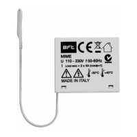
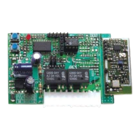
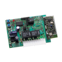
Two-relay two-channel receiver supplied directly from the mains 230V
50/60Hz, extremely compact, controlled by a microcontroller with decoding,
remote control self-learning, antijamming digital lter to improve radio per-
formance even further.
The rmware developed for this receiver is extremely exible and intuitive
and allows advanced functions such as the independent change of the oper-
ating modes for each channel.
This receiver is tted with an integrated buzzer that allows programming
without having to physically access the board.
It uses a SAW lter to improve selectivity and suppress out-of-band interfer-
ence.
Thanks to the use of suitably sized relays, with this receiver both lights and
electrical motors can be controlled.
This module is tted with a practical and ecient low-consumption power
supply unit (standby ≤0,3W) characterized by a wide range of operating volt-
ages and is also protected from overvoltages at the mains input.
Compliant with the I-ETS 300 220 and ETS 300 683 European standards.
This manual will describe only the programming procedures used to control
the lights. As to the programming procedures to control the motor see: www.
bft-automation.com/area-download/.
2) GENERAL SAFETY
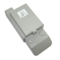
- The product is designed to operate only inside electrical junction boxes or
wall boxes, therefore its container is not protected against liquid penetration
but just basically protected against the contact with solid parts (IP20). The
use in environments other than those the product has been designed for is
strictly forbidden.
- It is forbidden to open or pierce the plastic container of the product, the parts
inside it are live; do not cut or strip the antenna wire since it is live.
- The device has no protection against overvoltages or short circuits on outputs,
therefore protection adequate to the installed load/s (fuse or circuit breaker)
must be provided.
- It is forbidden to install the receiver in SELV system sections (i.e. bell circuits,
video entry systems, 12/24V spot lights, etc.
)
3) APPLICATIONS
Remote control for blinds and shutters, wireless control to switch lights on,
lighting intelligent management, addition of light control points, energy
saving, domotics actuator, etc
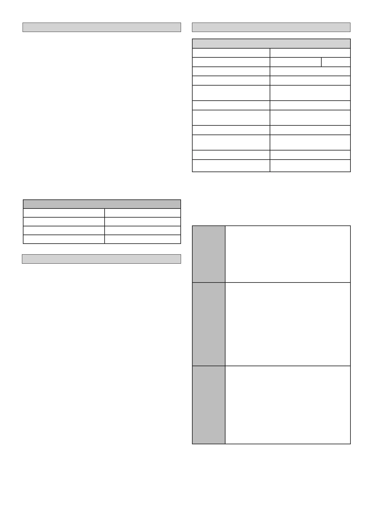
4) TECHNICAL SPECIFICATIONS
Power supply
110-230V~ 50/60 Hz*
Capacity of the output contacts 5A/1250VA @ 250VAC
Cosφ= 1
Output 2 relays, 5A max
Storage temperature
- 40 / + 100°C
Operating
temperature range
- 20 / + 40°C
IP rating
IP 20
Max. No. of transmitters that
can be stored
30
Built-in Rolling-Code radio-receiver
Frequency 433.92 MHz
Setting of parameters and
options
LED and BUZZER programming
button
Usable transmitters
ROLLING CODE transmitters
Maximum cable lengths of CH1
and CH2 inputs
4m, min Ø1,5 mm
2
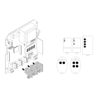
5) DIMENSIONS (FIG. A)
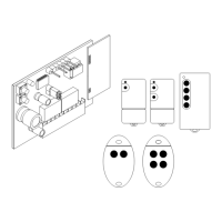
6) TERMINAL BOARD WIRING (FIG. B)
7) -
WIRING TO CHECK 2 INDEPENDENT LOADS, SUCH AS 2 BULBS FOR
INSTANCE
(FIG. C1).
-
WIRING TO CHECK 1 INDEPENDENT LOAD, SUCH AS 1 MOTOR FOR
INSTANCE
(FIG. C2) .
8) LIGHT OPERATION MODE
Monostable
The selected output is activated by pressing one of the
corresponding buttons of the remote control. If the output
is already active (for instance during the corresponding
activation of the local control), the following activation
command (i.e. the pressure of the corresponding button
on the remote control) is ignored.
In case of a voltage drop, when the supply is restored the
minireceiver maintains the status of the outputs (if the
status of the local inputs is not changed during the inter-
ruption).
Bistable
Outputs are controlled this way:
- rst pressure of the remote control button: the output sto-
red on the corresponding key is activated
- second pressure of the remote control button: the output
is deactivated
Moreover, when the local switch is closed and the relative
output is active, if the corresponding button of the remote
control is pressed, the output is deactivated; the output re-
activates when the switch is opened again.
Finally, bistable is the factory-set default mode; it is automa-
tically reset when the memory is erased.
In case of a voltage drop, when the supply is restored the
minireceiver maintains the status of the outputs (if the sta-
tus of the local inputs is not changed during the interrup-
tion).
Timed
In this mode the selected output is activated remotely
when one of the remote control buttons is pressed and
remains active for a period of time (timeout) stored in the
device. The output can be deactivated when the button is
pressed, after 5 seconds minimum.
The output can be controlled the same way also local-
ly. (Ex.: if the switch is closed, the output is activated for
the set time, after which it deactivates. If then the switch
opens, the output is activated and the timer restarts. The
change of status of the switch amounts to pressing the
remote control button: it causes the deactivation of the
output after 5 seconds minimum).
In case of a voltage drop, when the supply is restored, the
minireceiver keeps the lights OFF.
9) “MOTOR CONTROL” MODE FUNCTIONS
In the motor version there is a timeout (see g. D5) that the user can program,
used to stop the command received (by both TX and the local inputs) to
protect the motor.
The relays cannot be active at the same time.
A change in activation will be preceded by both deactivating for 500 ms mi-
nimum (400ms minimum).
D812969 90999_04
 Loading...