A
C
JP5 JP7
Y #
F2 3,15 AT
F1 1.25 AT(220-230V)
F1 2.5 AT (120V)
ANT.
ANT
SHIELD
24V
220-230V ~
*
S2
S1
S3
0,75
0,75
0,75
0,75
0,75
*
L N
10
11
L
N
M1
220-230V ~
*
14 15
20
21
26 27
40
41
42
43
44
45 50
51
52
60 61
62
70
71
72
73
74 75
+
M2
24V
AUX 3
(MAX 24V 1A)
- REF SWE
+ REF SWE
SWC 1 / SW 1 / ENC1A
SWO 1 / SW 2 / ENC1B
SWC2 / ENC2A
SWO2 / ENC2B
24V -
24V +
24 VSafe+
COM
IC 1
IC 2
COM
SAFE 1
STOP
FAULT 1
SAFE 2
FAULT 2
-
+
-
NO
NO
NC
NC
NC
JP20
3x2,5 mm
2
3x2,5 mm
2
230V
(*)
24V
(*) 110V
26
AUX 3 ≠ 1 AUX 3 = 1
27
1
26 27 50 51
24 V~
SCA
220
+ +
S1
X1
OPEN
S1
X1
STOP
- -
S2
X1
CLOSE
S2
X1
STOP
OPEN
CLOSE
ENGLISH
IT IS NECESSARY TO FOLLOW THIS SEQUENCE OF ADJUSTMENTS:
1 - Adjusting the limit switches
2 - Autoset
3 - Programming remote controls
4 - Setting of parameters/logic, where necessary
After each adjustment of the end stop position a new autoset is required.
After each modication of the motor type, a new autoset must be carried out
If the simplied menu is used:
- In GIUNO ULTRA BT A 20 GIUNO ULTRA BT A 50 - E5 BT A18 - E5 BT A12 motors: phase
1 (end stop adjustment) is included in the simplied menu.
- In other motors: phase 1 (end stop adjustment) must be carried out before activating
the simplied menu
D2D1
725150 70
24V ~
2
1
TX1
2
1
RX1
4
5
3
SAFE 1 = 0
SAFE 1 = 1
725150 70
24V ~
Vsafe
7352
2
1
TX1
2
1
RX1
4
5
3
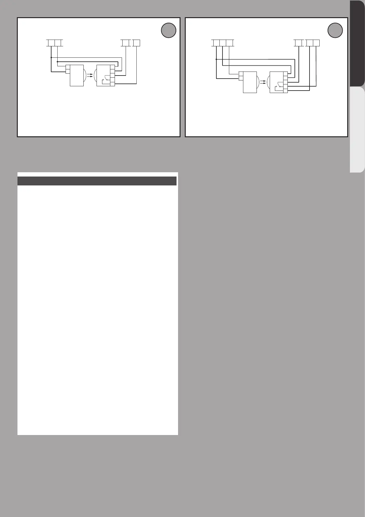
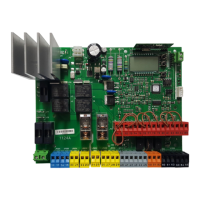
Photocells not checked (Check every 6 months)
Photocell checked
THALIA - 3
D814123 0AA00_01