Do you have a question about the BFT THALIA P and is the answer not in the manual?
Displays the product name in multiple languages on the front panel.
Illustrates the necessary preparation for tube and cable routing during installation.
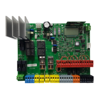
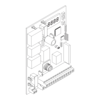
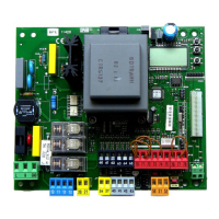
Shows the physical placement and identification of key components on the control unit board.
Provides wiring and limit switch connection examples for the ELI 250 BT motor.
Provides wiring and limit switch connection examples for the PHOBOS BT motor.
Provides wiring and limit switch connection examples for the IGEA BT motor.
Illustrates connection examples for LUX BT and LUX G BT motors, including limit switches.
Shows wiring and limit switch configurations for the SUB BT motor.
A flowchart detailing the sequence of menu options and navigation paths for programming.
Explains the symbols used in the menu navigation and provides brief descriptions for key functions.
Lists default and preset values for various operational parameters of the control unit.
Details the available logic functions and their configurable settings for system behavior.
Illustrates wiring connections for safety inputs SAFE 1, SAFE 2, and SAFE 3 for various configurations.
Shows wiring diagrams for safety inputs SAFE 4, SAFE 5, and SAFE 6, including different safety device types.
Guide on how to navigate and access different operational menus like Parameters, Logic, and Radio.
Lists common diagnostic codes, their descriptions, and troubleshooting notes for system errors.
Crucial safety guidelines for the installer regarding product use and potential hazards.
Specific warnings and best practices for electrical wiring installation to ensure safety.
Essential checks to perform on the automated system before final operation and during maintenance.
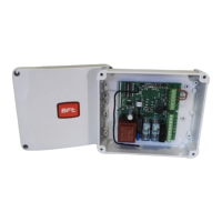
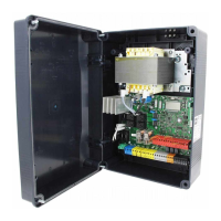
Details general information, technical specifications, and features of the control unit.
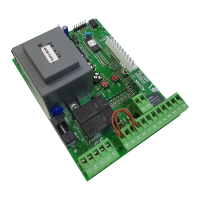
Explains the terminal board layout and provides initial wiring instructions for connections.
Describes the various configurable outputs for auxiliary functions like lights, alarms, and locks.
Details how input terminals can be configured for different commands like Start, Open, or Safety signals.
Explains how to configure safety inputs (SAFE) for photocells, safety edges, etc.
Step-by-step guide for testing the system, including autoset and impact force checks.
Instructions for adjusting limit switches, particularly for motors with encoders.
Defines parameters related to motor delay times for opening and closing operations.
Details parameters for adjusting motor speeds, deceleration, and leaf forces during operation.
Settings for motor type selection and automatic closing time parameters.
Configuration options for step-by-step operation and deadman safety modes.
Explains the ICE feature and settings for activating one or both motors.
Provides detailed definitions for configuring safety inputs like SAFE 1 through SAFE 6.
Details the mapping of auxiliary outputs to functions like radio channels, lights, or locks.
Instructions for programming transmitters, including wireless memorization and fixed-code operation.
Explains the configuration of inputs and outputs for expansion boards like EXPI2, EXPO1, EXPO2.
Settings for traffic light pre-flashing and access to the radio menu for transmitter management.
| Manufacturer | BFT |
|---|---|
| Model | THALIA P |
| Motor Voltage | 24V DC |
| Protection Rating | IP54 |
| Operating Temperature | -20°C to +55°C |
| Communication | U-Link |
| Protection Degree | IP54 |
| Power Supply Voltage | 230V ± 10%, 50/60 Hz |
| Inputs | Stop |
| Outputs | Flashing light |