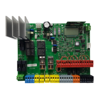
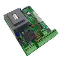
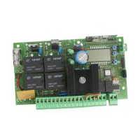
INSTALLATION MANUAL
Logic Denition
Default
Cross out
setting
used
Optional extras
AUX 1
Conguration of
AUX 1 output.
22-23
3
0 Output congured as 2nd Radio Channel.
1 Output congured as SCA (gate open light).
2 Output congured as Courtesy Light command.
AUX 2
Conguration of
AUX 2 output.
24-25
1
3 Output congured as Zone Light command.
4 Output congured as Stair Light
5 Output congured as Alarm
AUX 3
Conguration of
AUX 3 output.
26-37
0
6 Output congured as Flashing light
7 Output congured as Latch
8 Output congured as Magnetic lock
LOCK
Type of lock.
28-29
0
0
Output congured as 12V
solenoid latch.
1
Output congured as 12V
magnetic lock.
2
Output congured as 24V
solenoid latch.
3
Output congured as 24V
magnetic lock.
FIXED CODE
Fixed code 0
0
Receiver is congured for operation in rolling-code mode.
Fixed-Code Clones are not accepted.
1
Receiver is congured for operation in xed-code mode.
Fixed-Code Clones are accepted.
RADIO PROG
Transmitter pro-
gramming
1
0
Disables wireless memorizing of transmitters.
Transmitters are memorized only using the relevant Radio menu.
IMPORTANT: Disables the automatic addition of new transmitters, clones and replays.
1
Enables wireless memorizing of transmitters:
1- Press in sequence the hidden key and normal key (T1-T2-T3-T4) of a transmitter that has already
been memorized in standard mode via the radio menu.
2- Press within 10s the hidden key and normal key (T1-T2-T3-T4) of a transmitter to be memorized.
The receiver exits programming mode after 10s: you can use this time to enter other new transmitters.
This mode does not require access to the control panel.
IMPORTANT: Enables the automatic addition of new transmitters, clones and replays.
SERIAL MODE
Serial mode
(Identies how board
is congured in a BFT
network connection).
0
0 Standard SLAVE: board receives and communicates commands/diagnostics/etc.
1
Standard MASTER: board sends activation commands (START, OPEN, CLOSE, PED, STOP) to other
boards.
ADDRESS
Address 0
[ ___ ]
Identies board address from 0 to 127 in a local BFT network connection.
(see U-LINK OPTIONAL MODULES section)
EXPI1
Conguration of
EXPI1 input on
input-output expan-
sion board.
1-2
1
0 Input congured as Start E command.
1 Input congured as Start I command.
2 Input congured as Open command.
3 Input congured as Close command.
4 Input congured as Ped command.
5 Input congured as Timer command.
6 Input congured as Timer Pedestrian command.
7 Input congured as Phot (photocell) safety.
8 Input congured as Phot op safety (photocell active during opening only).
9 Input congured as Phot cl safety (photocell active during closing only).
10 Input congured as Bar safety (safety edge).
11
Input congured as Phot test safety (tested photocell).
Input 3 (EXPI2) on input/output expansion board is switched automatically to safety device test
input, EXPFAULT1.
12
Input congured as Phot op test safety (tested photocell active during opening only).
Input 3 (EXPI2) on input/output expansion board is switched automatically to safety device test
input, EXPFAULT1.
13
Input congured as Phot cl test safety (tested photocell active during closing only).
Input 3 (EXPI2) on input/output expansion board is switched automatically to
safety device test input, EXPFAULT1.
14
Input congured as Bar safety (tested safety edge).
Input 3 (EXPI2) on input/output expansion board is switched automatically to
safety device test input, EXPFAULT1.
ENGLISH
THALIA P 37