10
3. Applications
3.1 Vertical Upflow
• Vertical Upflow configuration is the factory set on all models (see Fig 1).
• If a side return air opening is required, field fabricate a return air plenum with an opening
large enough to supply unit and strong enough to support unit weight.
• If return air is to be ducted, install duct flush with floor. Use fireproof resilient gasket 1/8 to
1/4 in. thick between the ducts, unit and floor. Set unit on floor over opening.
IMPORTANT NOTE
Torque applied to drain connections should not exceed 15.ft.lbs.(see Fig.1&2)
3.2 Vertical Downflow
Conversion to Vertical Downflow: A vertical upflow unit may be converted to the
vertical downflow on it. Remove the door and indoor coil and reinstall 180° from
original position. See Fig. 2~3.
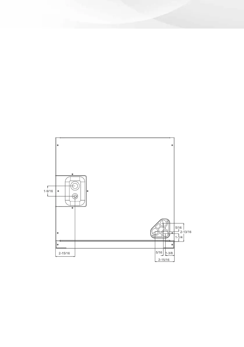
Fig2 Dimensions for
front connect coil