15
• Grounding may be accomplished by grounding metal conduit when installed in accord ance
with electrical codes to the unit cabinet.
• Grounding may also be accomplished by attaching ground wire(s) to ground lug(s) provided in
the unit wiring compartment.
• Ground lug(s) are located close to wire entrance on left side of unit (up-flow).
Lug(s) may be moved to marked locations near wire entrance on right side of unit (upflow). If
alternate location is more convenient.
• Use of multiple supply circuits require grounding of each circuit to lug(s) provided in unit.
4.3 Grounding
• Low voltage control connections are made to low voltage pigtails extending from top of air
handler (upflow position - see Figure 3). Connections for control wiring are made with wire
nuts. Control wiring knockouts (518 and 7/8) are also provided on the right and left side of the
unit for side connection.
• See wiring diagrams attached to indoor and outdoor sections to be connected.
• Make sure, after installation, separation of control wiring and power wiring has been
maintained.
e unit must be permanently grounded. FaIlure to do so can result In electrical shock causing
personal injury or death.
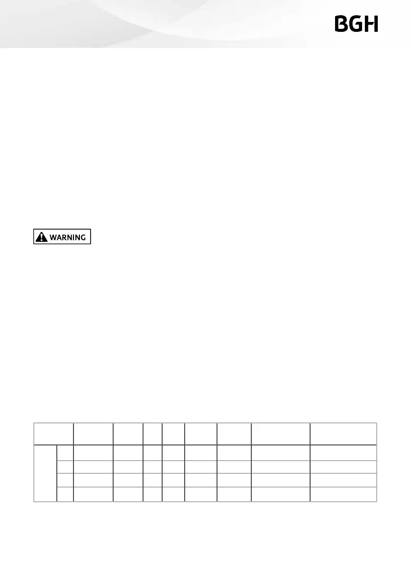
4.4 Electrical data
2
3
5
6
VOLTAGE
NOMINAL
COOLING
COOLING
& HEATING
HERTZ RPM SPEEDSHP
CIRCUIT
AMPS
MIN. CIRCUIT
AMPACITY
MAX. CIRCUIT
VOLTAGE HERTZ
220-240
220-240
220-240
220-240
50
50
50
50
701
794
845
963
0.6
1.4
3.3
4.3
1.0
1.8
4.1
5.4
15(A)
15(A)
15(A)
15(A)
3
3
3
3
1/5
1/2
3/4
3/4