GMV6 DC Inverter VRF Units Technical Sales Guide
125
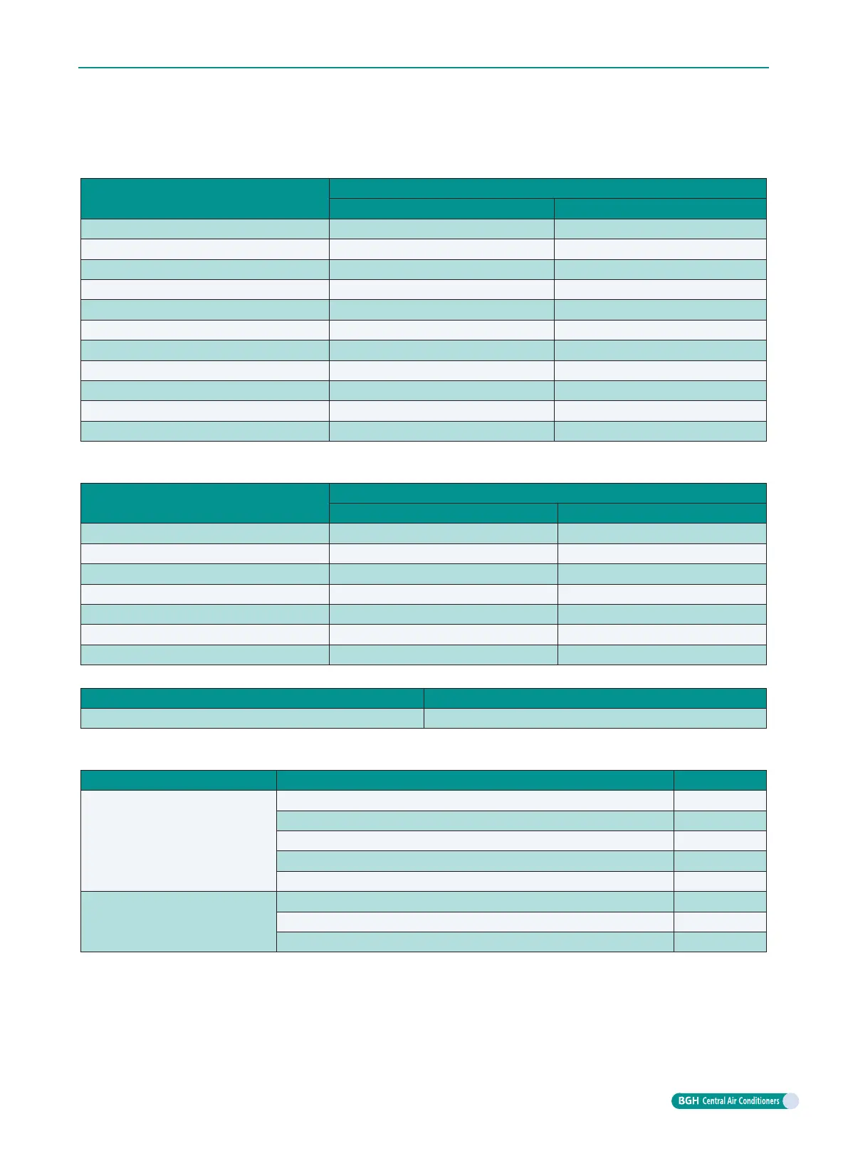
(3) Piping “D” of the IDU branches
Piping size of IDU branches shall be selected based on the total capacity of downstream IDU.
Total rated capacity X (kW) of downstream IDU
Piping size of indoor branches
Gas pipe (mm) Liquid pipe (mm)
X≤5.0
Φ
12.7
Φ
6.35
5.0<X≤14.2
Φ
15.9
Φ
9.52
14.2<X≤22.4
Φ
19.05
Φ
9.52
22.4<X≤30.0
Φ
22.2
Φ
9.52
30.0<X≤40.0
Φ
25.4
Φ
12.7
40.0<X≤45.0
Φ
28.6
Φ
12.7
45.0<X≤68.0
Φ
28.6
Φ
15.9
68.0<X≤96.0
Φ
31.8
Φ
19.05
96.0<X≤135.0
Φ
38.1
Φ
19.05
135.0<X≤186.0
Φ
41.3
Φ
19.05
186.0<X
Φ
44.5
Φ
22.2
(4) Piping “E” between the indoor branches and IDU
The piping size of IDU branches and IDU shall be consistent with that of IDU.
Rated capacity C (kW) of IDU
Piping size of indoor branch and IDU
Gas pipe (mm) Liquid pipe (mm)
C≤2.8
Φ
9.52
Φ
6.35
2.8<C≤5.0
Φ
12.7
Φ
6.35
5.0<C≤14.2
Φ
15.9
Φ
9.52
14.2<C≤22.4
Φ
19.05
Φ
9.52
22.4<C≤30.0
Φ
22.2
Φ
9.52
30.0<C≤40.0
Φ
25.4
Φ
12.7
40.0<C≤45.0
Φ
28.6
Φ
12.7
(5) Selection of outdoor modular branch “
①
”.
- Model
Selection of outdoor modular branch ML01/A
(6) Selection of branch “
②
”at indoor side
The branch of IDU shall be selected according to the capacity of downstream IDU.
R410A refrigerant system Total rated capacity of downstream IDU X (kW) Model
Y-shape branch
X<20.0 FQ01A/A
20.0≤X≤30.0 FQ01B/A
30.0<X≤70.0 FQ02/A
70.0<X≤135.0 FQ03/A
135.0<X FQ04/A
T-shape branch
C≤40.0 FQ14/H1
C≤68.0 FQ18/H1
68.0 < C FQ18/H2