EasyManua.ls Logo

BGS technic 2202 User Manual

BGS technic 2202
7 pages
To Next Page IconTo Next Page
Page #1 background imageLoading...
Page #1 background image
Art. 2202
DIGITAL CLAMP METER
STRUCTURE
1. Trigger Used to open and close the jaws.
2. Function / Range Switch Used to select desired function or range as well as to turn on or off the
meter.
3. Display
4. COM-Jack Plug-in jack for the black (Negative) test lead.
5.
Plug-in jack for the red (Positive) test lead.
6. "RANGE" Button Used to switch between autorange mode and manual range mode as well as to
select desired manual range.
7.
a. In resistance, AC/DC current or AC/DC voltage measurement, press this button to enter or exit
Data Hold mode.
b. In diode or continuity test function, press this button to switch between the diode and
continuity test functions.
8.
In current measurements, this button can be used for zeroing before
measurement. In other measurements, this button can be used to enter or exit relative mode.
The "ZERO" button must be pressed for compensation of measurement error in the 400A range.
9. Tactile Barrier
10. Jaw used for clamping the conductor for current measurements.
Introduction for the Built-in Buzzer
When you press a button Function / Range Switch, the buzzer will sound a beep if the press is
effective. Before the meter turns off automatically. The meter will give several short beeps, 1 minute
later it gives a long beep and then turns off automatically.
SAFETY INFORMATION
This meter has been designed according to IEC-81010 concerning electronic measuring instrument
with a measurement category (CAT II 600V) and Pollution degree 2.
WARNING
To avoid possible electric shock or personal injury, follow these guidelines:
x Do not use the meter if it is damaged. Before you use the meter, inspect the case. Pay particular
attention to the insulation surrounding the connectors.
x Inspect the test leads for damaged insulation or exposed metal. Check: the test leads for
continuity. Replace damaged test lead before you use the meter.
x Do not use the meter if it operates abnormally. Protection may be impaired. When in doubt, have
the meter serviced.
x Do not operate the meter around explosive gas, vapour or dusts.
x Do not apply more than the rated voltage, as marked on the meter, between terminals or between
any terminal and earth ground.
Question and Answer IconNeed help?

Do you have a question about the BGS technic 2202 and is the answer not in the manual?

BGS technic 2202 Specifications

General IconGeneral
Display TypeLCD
Display Digits3.5
Diode TestYes
Continuity TestYes
Battery Type9V
Safety RatingCAT II 600V
AC Voltage200V to 600V
DC Current200µA to 10A

Summary

STRUCTURE

Trigger

Button used to open and close the jaws.

Function / Range Switch

Selects desired function/range, turns meter on/off.

Display

Shows measurement readings.

COM-Jack

Plug-in jack for the black (Negative) test lead.

V•)+ Jack

Plug-in jack for the red (Positive) test lead.

RANGE Button

Switches between autorange and manual range modes.

HOLD/)

Enters/exits Data Hold or switches functions.

AZERO Button

Zeros meter for current or enters relative mode.

Tactile Barrier

Provides a safe gripping area.

Jaw

Clamps the conductor for current measurements.

Introduction for the Built-in Buzzer

Buzzer Operation

Indicates effective button presses and auto-off countdown.

SAFETY INFORMATION

General Safety Guidelines

Crucial warnings for safe operation and avoiding injury.

Additional Safety Precautions

Voltage Handling

Caution with voltages above 30V AC, 42V Peak, or 60V DC.

Finger Guards

Keep fingers behind guards on probes and meter.

Test Lead Connection Order

Connect common lead first, disconnect live lead first.

Hazardous Environments

Avoid explosive gas/vapors/dusts and use protective equipment.

CAT II Considerations

For low-voltage installations, not CAT III/IV.

CAUTION

Equipment Protection

Disconnect power and discharge capacitors before tests.

Proper Range Selection

Use correct function and range for measurements.

Switching Functions

Remove leads/jaws before changing function/range.

ELECTRICAL SYMBOLS

AC and DC Symbols

Symbols indicating Alternating and Direct Current.

Warning Symbols

Symbols for danger, electric shock, and ground.

CE Conformity

Indicates conformance to EU directives.

INSTRUCTION

General Description

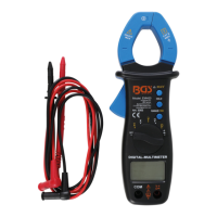
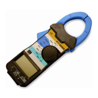
Overview of the digital clamp meter's capabilities.

GENERAL SPECIFICATION

Display Characteristics

3 3/4-digit LCD, max reading 3999.

Polarity and Over Range

Indication of negative polarity and over range.

Jaw Opening and Battery

Max conductor size and battery type.

Environment and Dimensions

Operating/storage conditions, size, and weight.

SPECIFICATIONS

Accuracy Statement

Accuracy specified for one year at 23°C ±5°C, up to 76% RH.

AC Voltage Specs

Range, resolution, accuracy, and overload protection for AC voltage.

DC Voltage Specs

Range, resolution, accuracy, and overload protection for DC voltage.

Resistance Specs

Range, resolution, accuracy, and overload protection for resistance.

Continuity and Diode Specs

Continuity Test Specs

Range, resolution, description, and overload protection for continuity.

Diode Test Specs

Range, resolution, description, and overload protection for diode test.

AC and DC Current Specs

AC Current Specs

Range, resolution, accuracy, overload, and temp coefficient for AC current.

DC Current Specs

Range, resolution, accuracy, overload, and temp coefficient for DC current.

OPERATION INSTRUCTION

Data Hold Mode

Enters Data Hold mode to freeze current reading.

Using Relative Mode

Stores a reference reading and zeros the display.

Manual Ranging and Autoranging

Entering Manual Range

Press 'RANGE' to enter manual mode; 'Auto' disappears.

Cycling Through Ranges

Press 'RANGE' to increase range; wraps to lowest.

Exiting Manual Range

Press and hold 'RANGE' for 2 seconds to return to auto mode.

Measurement Procedures

Measuring DC Voltage

Connect leads, set switch to V, read display.

Measuring AC Voltage

Connect leads, set switch to V, read display.

Measuring DC or AC Current

Set switch to A, zero, clamp jaws, read display.

Measuring Resistance

Connect leads, set switch to Ω, read display.

Advanced Measurement Tests

Diode Test

Test forward voltage drop of a diode.

Continuity Test

Test for continuity with a built-in buzzer.

Meter Features and Maintenance

Automatic Power-off

Meter turns off automatically after 15 minutes of inactivity.

MAINTENANCE

Instructions for cleaning the meter case and terminals.

BATTERY REPLACEMENT

Procedure for replacing the meter's batteries.

EU Declaration of Conformity

Conformity Statement

Declares compliance with EU directives and standards.

Related product manuals