7 4
T
u
r
n
b
y
1
8
0
°
T
u
r
n
b
y
1
8
0
°
④When power of the receiver is turned ON, LOW mode (inclination: 0.1mm - 0.8mm) is selected.
If the LED (red) in the 0.08. position blinks, inclination exceeds 0.8.
Levelling at
LOW mode
Change to
HIGH mode
Levelling at
HIGH mode
OPERATIONS
5.OPERATIONS
5-1.Levelling operation
①Remove oil, dirt, notches and marks from the machine table's surface and from the base of the device.
②Place the device carefully on the reference surface
parallel to the X and Y axes.
X-axis
Y-axis
③Push the POWER switch to turn ON the power of
Body/Receiver.
⑤Adjust the level in order to turn on the LED (blue) of the central position. When the LED (blue) turns
on, the inclination is within 0.1.
When the inclination of one of the axes is adjusted within 0.1, the LED (blue) turns on and the buzzer
emits a sound [Beep, beep].
When the inclination of both axes is within 0.1, the LED (blue) turns on and the buzzer emits a
sound [Beep-beep-beep].
HIGH
⑥Push the MODE switch to change to the mode.
⑦Adjust the level in order to turn on the LED (blue) of the central position.
When the inclination of one of the axes is adjusted within 0.01, the LED (blue) turns on and the
buzzer emits a sound [Beep, beep]. When the inclination of both axes is within 0.01, the LED
(blue) turns on and the buzzer emits a sound [Beep-beep-beep].
ContinuousLED(blue)
ContinuousLED(blue)
4.BEFORE USING THE DEVICE
BEFOREUSING THE DEVICE
4-1.Environmental settings
4-2.How to execute the zero adjustment
If there is a difference in the temperature between the storage location and the utilization location,
leave the device for a certain amount of time in the utilization location to perform the average
environmental settings (temperature, humidity).
When the Level MasterWireless(Body/Receiver) is turned on, depending on the utilization
environment and on the status of the reference surface measured, the level position may not be
always the "0" position (continuous blue LED). Execute every time the reference settings by
means of zero adjustment in accord with the utilization environment.
③Push the POWER switch to turn ON the power.(Body/Receiver)
④Execute the zero adjustment and the levelling checks following
the procedures below.
②Use as reference the line markers on the base of the Body and
mark 4 points in the X and Y directions on the reference surface.
4 markings
①Position the Body on the reference surface. When placing the
device, remove oil and dirt from its base and also remove notches,
oil and dirt from the reference surface of the precision plate.
(Example: If the difference in the temperature is 10℃, leave the device for 15~20 minutes.
)
Caution
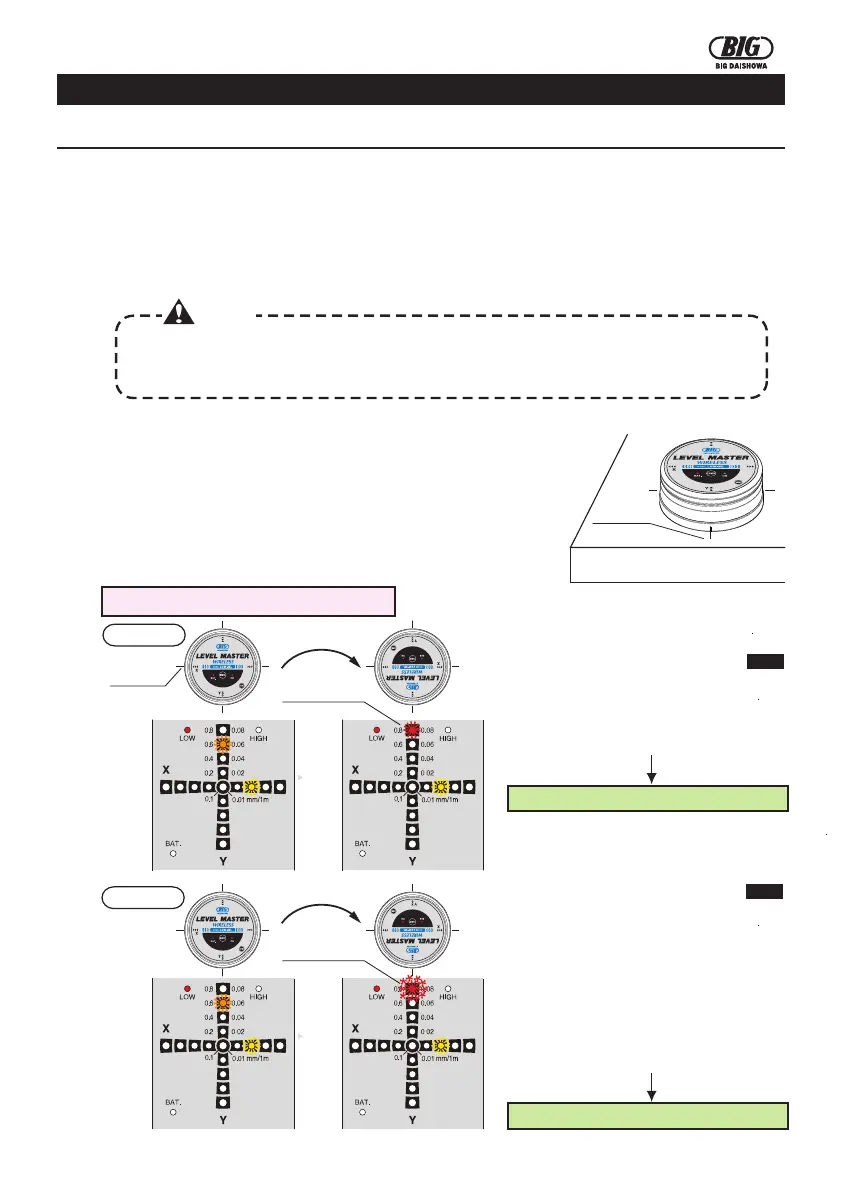
How to check the levelling value in LOW mode
Case 2
Case 1
marking
Blinking LED (red)
Continuous LED (red)
②The levelling value of both axes is
within 0.8 after turning the device by
180°.
①The levelling value of the X and Y axes
is within 0.8 after switching to the LOW
mode.
Go to P5 →How to execute the zero adjustment in LOW mode
Go to P5 →How to execute the zero adjustment in LOW mode
②The levelling value of one of the axes
exceeds 0.8 after turning the device by
180°.
①The levelling value of the X and Y axes
is within 0.8 after switching to the LOW
mode.
③Adjust the level of the reference
surface in order to obtain a levelling
value within 0.8 for both axes.