Do you have a question about the bihl+Wiedemann BWU3543 and is the answer not in the manual?
| Brand | bihl+Wiedemann |
|---|---|
| Model | BWU3543 |
| Category | Gateway |
| Language | English |
Read all instructions carefully before working with the device. Consider safety guidelines.
Important safety information regarding installation, voltage, and personal protection.
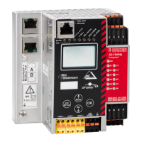
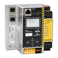
Details of the device's front panel, including ports, indicators, and controls.
Explanation of the different LED states and their meanings for device status.
Description of input terminal functionality and configuration options.
Description of output terminal functionality, protection, and configuration.
Details on clock outputs (T1, T2) and power supply terminals (0V, 24V).
Specifications for ambient operating temperature and cable temperature ratings.
EMC considerations and requirement for using copper conductors.
Warnings about connecting slaves/repeaters to power supply cables and ASi circuit cables.
Procedure for switching the device's power supply to ASi Power24V.
Diagram illustrating a typical ASi circuit setup with gateway and slaves.
Explanation of symbols used in the ASi network structure diagram.
Wiring diagram for connecting floating contacts to the device's terminals.
Wiring diagram for connecting antivalent contacts to the device's terminals.
Wiring diagram for connecting a contactor to the device's terminals.
Wiring diagram for connecting OSSDs (Optical Safety Devices) to the device.
Configuration and explanation for 1-channel speed monitoring on local connections.
Configuration and explanation for 2-channel speed monitoring on local connections.
Setting up device output SO1 to function as a standard input.
Setting up device outputs SO1 and SO2 to function as safe inputs.
Important: Commission the gateway before the safety unit.
Steps for creating, downloading, acknowledging, and validating configurations.
Adjusting master config for safety monitor address and referring to ASIMON360 manual.
Information on using the Ethernet diagnostic interface for Safe Link communication.
Devices must be connected via an external switch for Safe Link communication.
Steps for commissioning the device through its interface and display modes.
Steps to select the Modbus TCP protocol for device operation.
How to view Ethernet interface settings such as IP address and MAC ID.
Procedure for configuring the watchdog timer for device operation.
Steps to select the EtherNet/IP protocol and activate it.
Restart the device for the selected configuration changes to take effect.
Setting IP address, net mask, and gateway for EtherNet/IP.
Procedure for connecting ASi slaves to the gateway and searching for them.
Enables simple and quick configuration of all connected ASi circuits.
Options to save configuration in Run or Project mode.
Flowchart illustrating the device configuration steps and outcomes.
Hotkey combination to initiate the Store+Run configuration process.
Steps to assign addresses to ASi slaves, including connecting new slaves.
Methods for setting parameters directly on the device or via chip cards.
Detailed scenarios for chip card compatibility, data synchronization, and error handling.
How to identify faulty ASi slaves using the device display.
How to view the last recorded error message on the device.
Procedure for replacing a defective safety-related ASi slave with a new one.
Procedure for replacing a defective device, particularly when Safe Link is used.
Importance of teaching the group manager after replacing a device with Safe Link.
Steps for copying bank A data to monitor, master, and configuration.
Procedure for teaching Safe Link to the group manager after device replacement.
Overview of menu navigation for device setup and diagnostics.
Steps for managing Safe Link, including stopping, starting, and node replacement.
Procedure for safely replacing the chip card, emphasizing power-off.
Handling situations where chip card and device configurations differ.
Handling situations where safety and ASi configurations differ.
Procedures for handling data differences and entering the PIN.
Overview of device menu options for setup, diagnostics, and settings.
Steps for selecting banks, stopping/starting the monitor, and copying data.
Confirmation when safety and ASi configurations are identical.
Overview of various AS-i Master gateways with different communication protocols.
Overview of different ASi digital input/output modules.
Overview of different ASi analog input/output modules.
Overview of available software tools for ASi systems.
Overview of various ASi circuit board modules for different applications.
Overview of ASi drive solutions for motor control and automation.
Overview of ASi modules for specialized functions like counters and couplers.
Overview of ASi circuit extension components like repeaters and terminators.
Overview of different ASi power supply units for the ASi system.
Overview of safety monitors, PROFIBUS/PROFINET gateways, and safety I/O modules.