Traction Handles
Leg Support
Housing
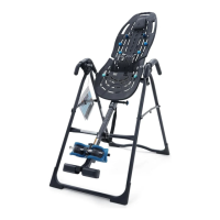
STEP 3
ASSEMBLE LAP PAD TO LAP PAD FRAME
Figure 3
Locate the Lap Pad Assembly Hardware Kit (D11020).
Figure 3: In this step, use only the four (4) small screws.
Position the Lap Pad Frame on top of the Lap Pad face-
down with the Leg Support Shaft Housing resting inside
the indented area of the Lap Pad. Align the screw holes.
Insert the screws through the holes and tighten with the
Screwdriver.
Screws x4
Leg Housings
FIGURE 4
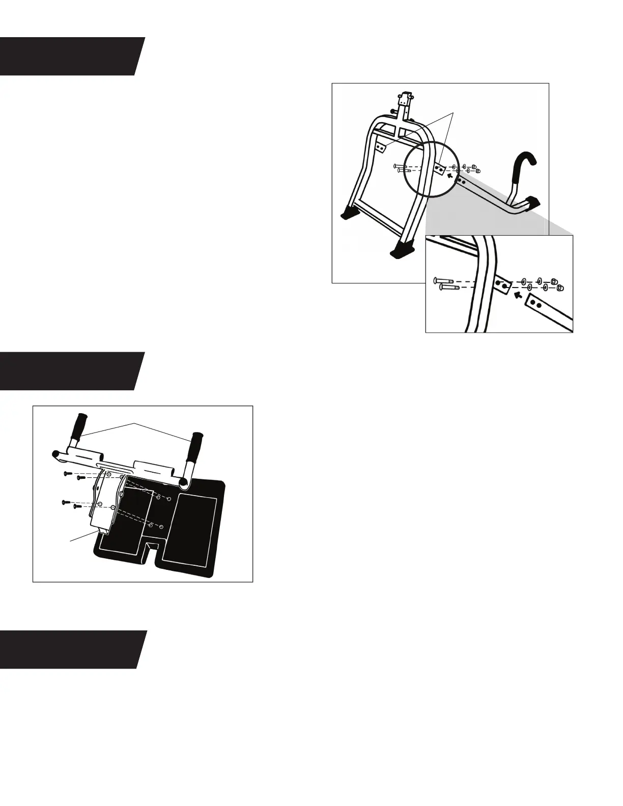
ATTACH LEGS TO BASE
STEP 2
Locate the Base Assembly Hardware Kit (D11019).
Figure 2a: With the Cane Handle facing upward, insert
one Leg into the Leg Housing of the Base Frame until
the two bolt holes align. Insert two Threaded Bolts from
the inside of the Leg Housing through the holes. Secure
on the outside of the Leg Housing using the Flat Washer,
Lock Washer and Bolt Cap, in that order.
Figure 2b: Tighten with the Wrenches provided. Repeat
with the other Leg.
Figure 2a
Figure 2b
Bolts x2
Flat Washer, Lock
Washer, Bolt Cap x2
Locate the Lap Pad Assembly Hardware Kit (D11020).
Figure 4a-4b: Use the remainder of the Lap Pad Hardware Kit (D11020) from Step 3. Thread the Hex Bolt
through a Flat Washer and Spacer. Make sure the small end of the Spacer faces away from the head end of
the Hex Bolt.
STEP 4
SECURE LAP PAD TO BASE ASSEMBLY
6