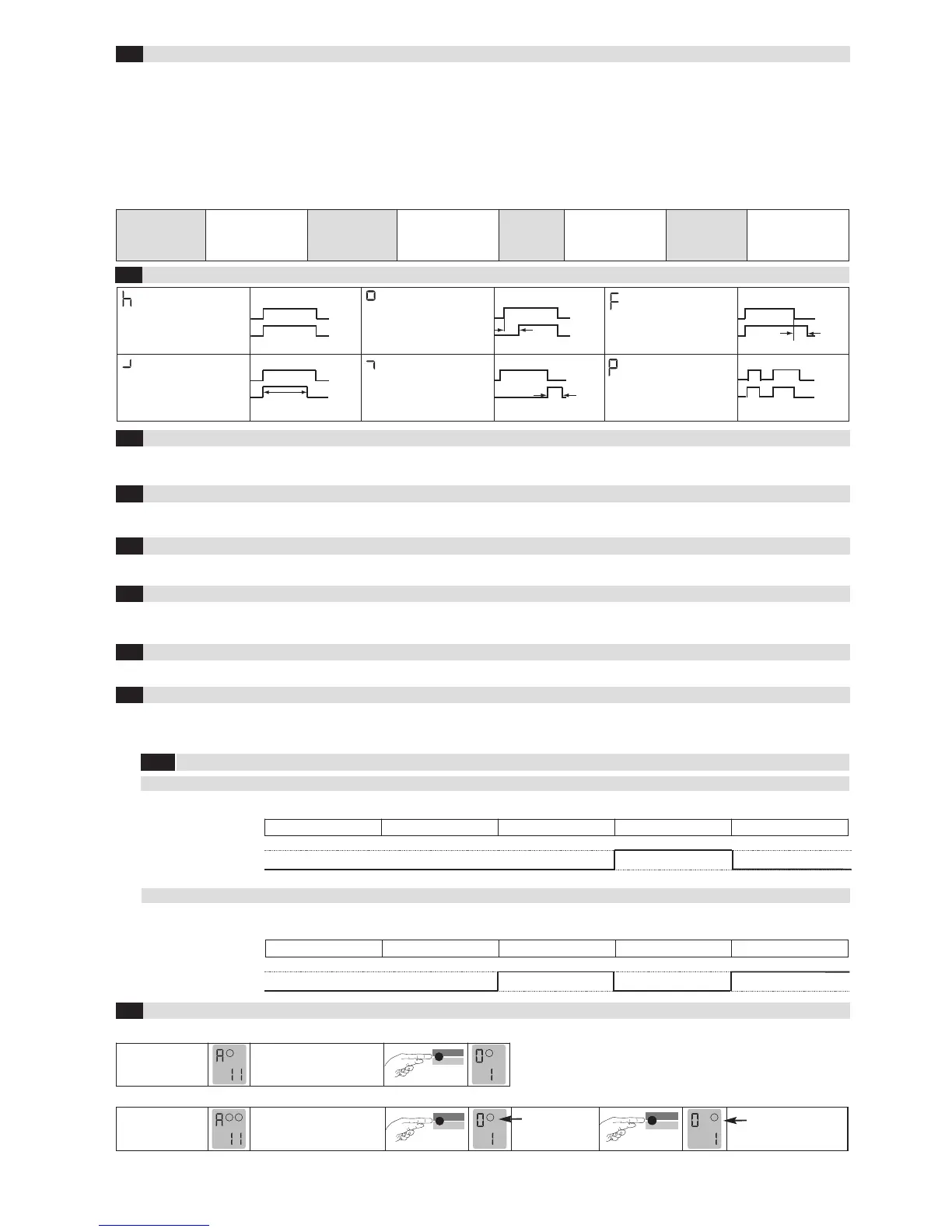
1.Door/gate
systems
A malfunction causes
the output relay to be
released. The alarm
relay drops out.
2. Barrier
A malfunction causes
the output relay to pick
up. The alarm relay
drops out.
3. Quiescent
current
A malfunction causes
the output relay to be
released. The alarm
relay drops out.
4. Direction logic
(2-loop device
only)
A malfunction causes
the output relays to be
released. The alarm
relay drops out.
*factory settings
Note: The set parameter values are retained after a power failure, independent from the “Protection against power failure” function.
P 1 = Protection against power failure activated: The sensitivity is restricted to 1–5.
Time functions 1 , time unit 2 and time factor 3 (Einstellungen siehe Tabelle 4.11a)
4.3
Parameters
1: Door and gate The assigned output relay picks up when the loop is activated and drops out when the loop returns to a non-activated condition.
2: Barrier The assigned output relay picks up when the loop is activated and drops out when the loop returns to a non-activated condition.
3
: Quiescent current The assigned output relay drops out when the loop is activated and picks up again when the loop returns to a non-activated condition.
4: Direction logic Output 1 switches if an object moves from loop 1 to 2. Output 2 switches if an object moves from loop 2 to 1. Both loops must be
activated for a short time. The outputs are reset again when loop 2 returns to a non-activated condition. Both loops must have re-
turned to a non-activated condition for another direction detection.
0: Loop 2 Loop 2 can be deactivated in a 2-loop device.
Basic functions 0 (see Table 4.11a for settings)
4.2
Signal characteristics with protection against power failure active (Function 9 = 1)
4 .9.1
For Activation (e.g. Barriers)
Basic function 0 = 2 Barrier systems
Without power Initialisation Free Occupied Free
For Safeguarding (e.g. Barriers, bollards)
Basic function 0 = 3 Quiescent current
Without power Initialisation Free Occupied Free
open (no)
closed (nc)
open (no)
closed (nc)
Output
Output
The sensitivity 5 (=Sensitivity) of the loop detector can be adapted in 9 stages: 51 = Lowest sensitivity, 59 = Highest sensitivity,
54 = Factory setting.
In a device with 2 outputs, output 2 can be either activated or deactivated. In ProLoop 11, output 2 can also be set as an alarm output.
Four different frequencies F1, F2, F3, F4* can be set in order to avoid interference when using several loop detectors.
The direction logic function can only be used with a 2-loop device. Direction logic must have been set in the basic function (see chapter 4.2). Detection
can be performed from: ➝ Loop 1 to loop 2 ➝ From loop 2 to loop 1 ➝ from both directions
ASB (=Automatic Sensitivity Boost). ASB is required in order to be able to recognise trailer drawbars after activation.
Sensitivity 4 (see Table 4.11a for settings)
4.4
Automatic Sensitivity Boost ASB 5 (see Table 4.11a for settings)
4.5
Frequency 6 (see Table 4.11a for settings)
4.6
Direction logic7 (see Table 4.11a for settings)
4.7
Output 2 8 (see Table 4.11b for settings)
4.8
Protection against power failure 9 (see Table 4.11a for settings)
4.9
Display after start-up:
 Loading...