11
6) Main Extension Arm Assembly
Slide the Main Extension Arm (B) over the top of
the Vertical Post (A) and attach to the lower
pivot tube with a 3/4” X 12 1/2” Hex Bolt (P) and
a 3/4” Lock Nut (Q).
NOTE: Tighten the lock nut down and
then back off a 1/4 turn to allow the
joint to pivot when adjusting the
system up and down.
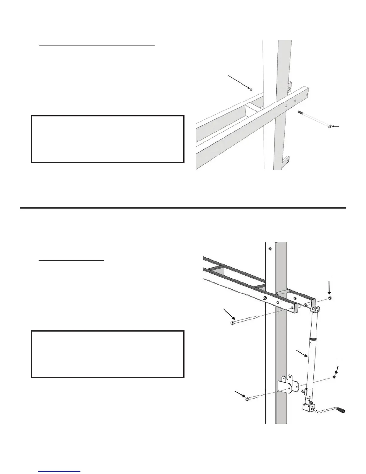
7) Actuator Assembly
Attach the Crank Adjustment Cylinder (F) using
a 3/4” X 12 1/2” Hex Bolt (P) and 3/4” Lock Nut
(Q) at the top and 5/8” X 6” Hex Bolt (H) with
5/8” Lock Nut (J) at the bottom.
NOTE: Tighten the lock nuts down
and then back off a 1/4 turn to allow
the joint to pivot when adjusting the
system up and down.
(Q)
(P)
(Q)
(P)
(H)
(F)
(J)
REV. 10/10/17