12
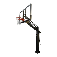
8) Spring Assist Assembly
Attach Spring-Assist Cartridges (E) to the
Main Extension Arm (B) using a 3/4” X 12 1/2”
Hex Bolt (P) and 3/4” Lock Nut (Q). The
Orange Rim Height Indicator (G) must slide
onto the 3/4“ x 12 1/2” Hex Bolt (P) on
whichever side you wish to install the height
indicator label shown in instruction #14. In
order to attach both Spring-Assist Cartridges
(E) at the bottom, lower the open end of each
Spring-Assist Cartridges (E) down over the
top of each welded tab as shown in the
diagram. You will use the Crank Adjustment
Cylinder to help align the lower mounting
holes. Use the 5/8” X 8” Hex Bolt (I) and 5/8”
Lock Nut (J) to attach them to the welded
tabs. You may need to turn or rotate the
Spring-Assist Cartridges (E) to line up holes.
The Rim Height Indicator (G) should hang
freely along the ouside of one of the
Spring-Assist Cartridges (E). Next, remove
and discard the plastic spring assist spacer
from Spring-Assist Cartridges (E).
NOTE: Tighten the lock nuts down
and then back off a 1/4 turn to allow
the joint to pivot when adjusting the
system up and down.
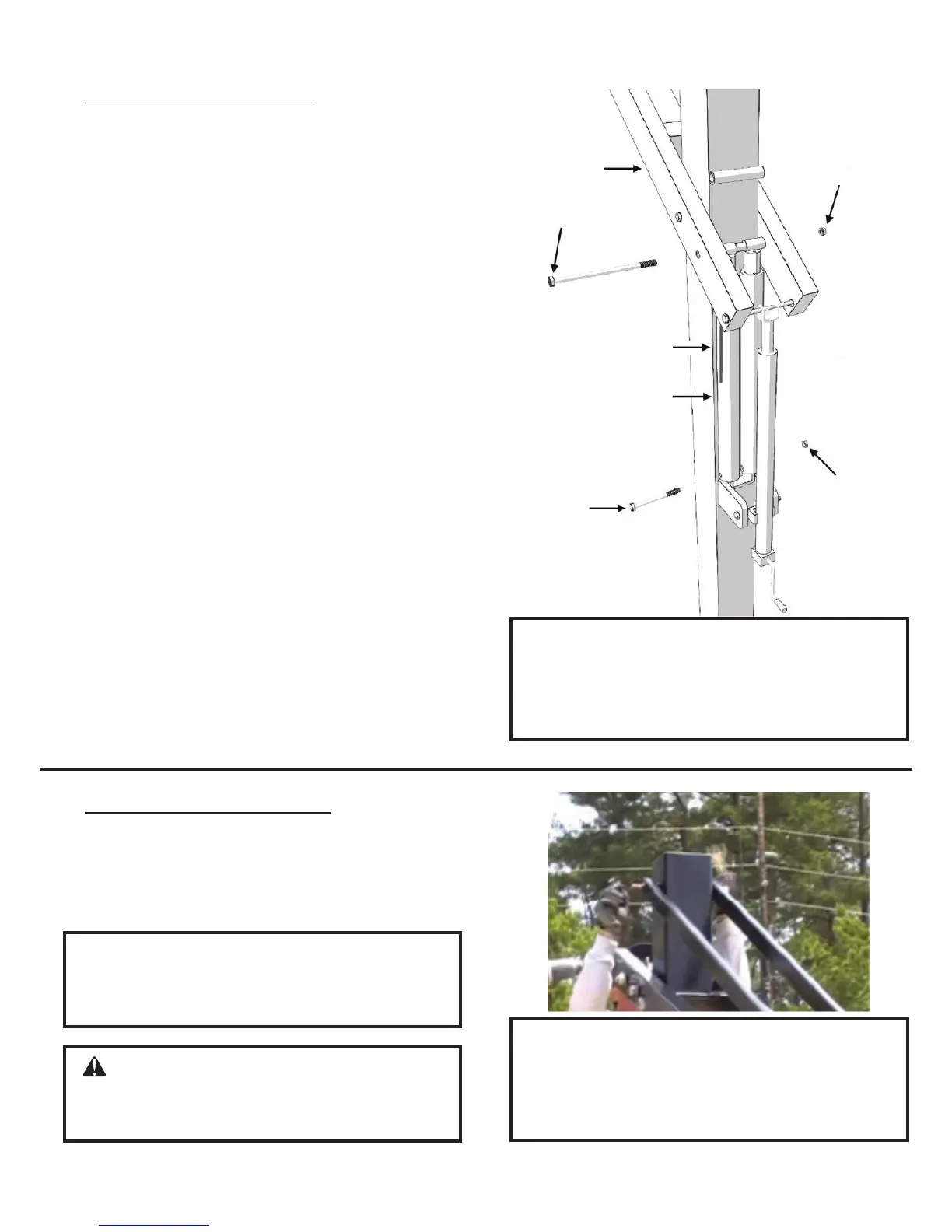
9) Upper Linkage Assembly
Attach Parallel Linkages (C) to Vertical
Post (A) with a 3/4” X 11 1/4” Hex Bolt (O)
and a 3/4” Lock Nut (Q).
NOTE: Tighten the lock nuts down
and then back off a 1/4 turn to allow
the joint to pivot when adjusting the
system up and down.
CAUTION: Injury may occur if
linkages are allowed to fall from main
arm during assembly.
NOTE: It does not matter which end
of the parallel link you attach to the
vertical post.
(B)
(Q)
(P)
(G)
(J)
(I)
(E)
REV. 10/10/17