J
Jeremy HartAug 2, 2025
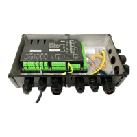
What to do if Bitzer CM-SW-01 Control Unit relays are not energized after power on?
- SSean BrownAug 2, 2025
If the relays in your Bitzer Control Unit aren't energizing after powering on and reapplying the run signal, try the following: * Turn off the power for 5 seconds and check if the relays energize upon restart. * If the PTC-sensor temperature is too high (resistance above 11.4 kΩ ±20%), the fault relay will release to protect the motor. * A broken connection to the PTC-sensor (resistance more than 1 MΩ) will also prevent relay engagement. * A short circuit on the PTC-sensor cables (resistance near zero Ω) will disable overheat protection. * If all three phases are within range and resistance is below 2.9 kΩ ±20%, the compressor module may be defective and require replacement.