10
3.4 Start unloading (SU) and
Capacity control (CR)
The upper parts of the valves are
delivered separately packed to avoid
transport damage. These valve parts
must be fitted in place of the sealing
flanges before the compressor is
evacuated.
Warning!
Compressor is under pressure
by holding charge!
Severe injuries possible.
Release the pressure in the
compressor!
Wear safety goggles!
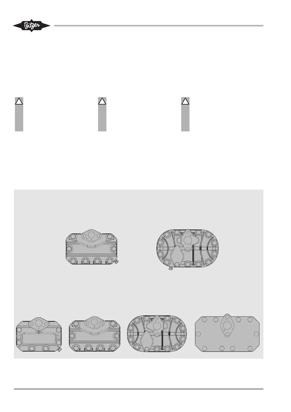
To avoid mistakes the cylinder head
and the valve flange are marked with
a coding (SU resp. CR). A pin in the
flange surface allows only the correct
assembly. (see figure 3).
3.4 Démar ra ge à vide (SU) et
Régulation de puis san ce (CR)
Les parties supérieures des vannes sont
livrées séparément afin d'éviter des dété-
riorations durant le transport; elles doivent
être montées avant la mise sous vide.
Pour cela, il faut remplacer la bride d'obtu-
ration par la partie supérieure de la vanne.
Avertissement !
Compresseur est sous pression
par gaz de protection !
Graves blessures possibles.
Retirer la pression sur le compres-
seur !
Porter des lunettes de protection !
Pour évi ter les confu sions, la tête de
cylin dre et la bride de la vanne sont iden -
ti fiées avec un indi ce (SU ou plutôt CR).
Une gou pille de posi tion ne ment logée
dans la bride assure un assem bla ge cor -
rect (voir figure 3).
3.4 Anlaufentlastung (SU) und
Leistungsregelung (CR)
Die Ventil-Oberteile werden zum
Schutz gegen Transportschäden als
Beipack geliefert. Sie müssen vor
dem Evaku ieren montiert werden.
Dazu den Blindflansch gegen das
Oberteil wechseln.
Warnung!
Verdichter steht unter Druck
durch Schutzgas!
Schwere Verletzungen möglich.
Verdichter auf drucklosen
Zustand bringen!
Schutzbrille tragen!
Um Verwechslungen zu vermeiden,
sind Zylinderkopf und Ventilflansch
gekenzeichnet (SU bzw. CR). Ein
Pass-Stift in der Flansch fläche erlaubt
nur die richtige Positio nie rung (siehe
Abbildung 3).
KB-104-4
Abb. 3 Zylinderköpfe für Anlaufentlastung /
Leistungs regelung
Fig. 3 Cylinderheads for Start Unloading /
Capacity Control
Fig. 3 Têtes des culasses pour démarrage
à vide / Régulation de puis san ce
Anlaufentlastung / Start Unloading / Démarrage à vide
Leistungsregelung / Capacity Control / Régulation de puissance
4VE(S)-6Y .. 4NE(S)-20(Y)
4JE-13Y .. 6FE-50(Y)
4FES-3(Y) .. 4CES-9(Y)
4VE(S)-6Y .. 4NE(S)-20(Y)
4JE-13Y .. 6FE-50(Y)
8GE-50(Y) .. 8FE-70(Y)
SU
CR