EasyManua.ls Logo

Bitzer ECOLITE LHL5E/4CES-6Y User Manual

Bitzer ECOLITE LHL5E/4CES-6Y
96 pages
To Next Page IconTo Next Page
Page #1 background imageLoading...
Page #1 background image
KB-206-1
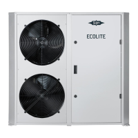
ECOLITE
Air-cooled condensing units with capacity-controlled ECOLINE compressors
English....................................................................................................................................................... 2
ECOLITE
Luftgekühlte Verflüssigungssätze mit leistungsgeregelten ECOLINE Verdichtern
Deutsch ..................................................................................................................................................... 33
ECOLITE
Groupes de condensation refroidis par air avec compresseurs ECOLINE dotés d’une fonction de régu-
lation de puissance
Français..................................................................................................................................................... 64
LHL3E/2EES-2Y
LHL3E/2DES-2Y
LHL3E/2CES-3Y
LHL5E/4FES-3Y
LHL5E/4EES-4Y
LHL5E/4DES-5Y
LHL5E/4CES-6Y
Document for installers
Dokument für Monteure
Document pour des monteurs

Table of Contents

Other manuals for Bitzer ECOLITE LHL5E/4CES-6Y

Question and Answer IconNeed help?

Do you have a question about the Bitzer ECOLITE LHL5E/4CES-6Y and is the answer not in the manual?

Bitzer ECOLITE LHL5E/4CES-6Y Specifications

General IconGeneral
BrandBitzer
ModelECOLITE LHL5E/4CES-6Y
CategoryHeat Pump
LanguageEnglish

Summary

Safety

Authorized Staff

Specifies that only qualified and authorized personnel should perform work on the unit.

Residual Risks

Highlights unavoidable residual risks associated with the unit and emphasizes careful reading of instructions.

Safety References

Defines safety references as hazard prevention instructions that must be strictly followed.

Electrical Connection

Schematic Wiring Diagram

Presents the schematic wiring diagram for ECOLITE condensing units with component abbreviations.

Commissioning

Setting the Controller

Details parameters to be set on the ECOLITE controller before commissioning.

First Power On Procedure

Outlines the procedure for the initial power-up and self-test of the controller.

Controller Software Parameters

Active Software Settings

Lists parameters for active software settings like set points for pressure and temperature control.

Alarm and Time/Date Settings

Registered Alarms Information

Describes the alarm memory, its locations, and how to retrieve alarm numbers and dates.

Controller Date/Year and Active Alarms

Displaying Active Alarms

Explains how to view the currently active alarm message on the controller display.

Programming Menu - System Configuration

Refrigerant Type Configuration

Details how to set the refrigerant type in the system via the programming menu.

Controller Settings - Compressor and CR II

Programming Menu - Fan Control

Cold Store Control and Emergency Service

Emergency Service Modes

Details manual operation modes for emergency situations when faults occur.

Emergency Operation and Application Limits

Monitoring Application Limits

Defines limits for condensing pressure, suction pressure, and discharge gas temperature.

Application Limit Monitoring and Digital Inputs

Alarm Messages

Fault Sensor Alarms

Describes alarms related to faults in ambient, cold store, and discharge gas temperature sensors.

Application Limit Alarms

Details alarms for exceeding application limits like high pressure or low suction superheat.

Communication

Operation

Regular Tests

Lists essential checks to be performed regularly by a specialist on the condensing unit.

Decommissioning

Related product manuals