◈ Information
This installation guide contains quick information required for the product
installation. Refer to the User’s Manual in the CD that comes with the product for
detailed installation instructions. The CD contains the following information.
1. Manual: User’s Manual, Code table, and Control commands
2. Driver: Windows driver and OPOS driver
3. Utility: Logo download tool and virtual memory switch adjustment tool
We at BIXOLON maintain ongoing efforts to enhance and upgrade the functions
and quality of all our products. In following, product specifications and/or user
manual content may be changed without prior notice.
◈ Checking the Contents
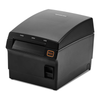
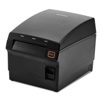
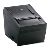
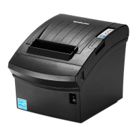
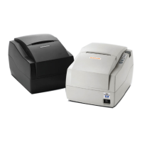
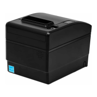
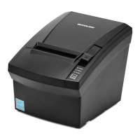
SRP-F310/312/313II
Power Cord
Paper Roll
Procuct Installation CDProcuct Installation CD
CD
Installation Guide
Connectin
Cables◈
1. Turn off the printer and ECR (host computer).
2. Connect the power cord to the adapter and connect the adapter to the power
supply connector of the printer.
3. Check the type of the interfaces at the back of the printer (Serial, Paralle, USB,
Ethernet, Powered USB, Wireless LAN, Bluetooth), and connect the interface
cable.
4. Connect the drawer kick-out cable to the drawer kick-out connector of the
printer.
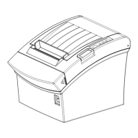
◈ Installing Paper Rolls
1. Press the [Open Cover] button and
open the cover.
2. Insert new paper roll in the correct
direction.
3. Pull the paper slightly, and close the
cover.
※ Note
When closing the cover, hold down
the center of the cover so that the
paper is closely attached to the roller.
Printing quality may not be optimum
if recommended paper is not used.
(Refer to the User's Manual.)
※ Do not use paper wider than 80 mm or plastic paper tube when using a
printer that specifies
80 mm paper.
Using 83mm Paper◈
Remove the partition installed in the printer to use 83mm roll paper.
※ Refer to the User’s Manual for detailed instructions on how to remove the
partition safely.
◈ Using Operation Panel
• POWER indicator
Blue light will be on when power is supplied to the printer.
• ERROR indicator
Red light will be on for error conditions such as no paper or open cover.
• PAPER indicator
Red light will be on when the paper is about to run out or if there is no paper. If
this light keeps blinking, it means either self test state or macro execution standby
state.
• FEED button
Press feed button to feed the paper. Pressing and holding the feed button will feed
the paper continuously.
◈ DIP switch setting
DIP switch setting must be done while the printer is turned off. Changes during
power on are not recognized.
1. Serial interface setting
• DIP switch 1
Switch Function ON OFF Default
1-1 Auto-Cutter Selection Disable Enable OFF
1-2 Handshaking XON/XOFF DTR/DSR OFF
1-3 Word length 7 bit 8 bit OFF
1-4 Parity check YES NO OFF
1-5 Parity selection EVEN ODD OFF
1-6
Baud rate (bps) Refer to Table 1 shown below
OFF
1-7 ON
1-8 OFF
2. Parallel / USB / Ethernet / Wireless LAN / Powered USB interface setting
• DIP switch 1
Switch Function ON OFF Default
1-1 Auto-Cutter Selection Disable Enable OFF
1-2 N/A - - OFF
1-3 N/A - - OFF
1-4 N/A - - OFF
1-5 N/A - - OFF
1-6 N/A - - OFF
1-7 N/A - - OFF
1-8 N/A - - OFF
3. Bluetooth interface setting
• DIP switch 1
Switch Function ON OFF Default
1-1 Auto-Cutter Selection Disable Enable OFF
1-2 N/A - - OFF
1-3 SSP Mode Enabled Disabled OFF
1-4 N/A - - OFF
1-5 N/A - - OFF
1-6 N/A - - OFF
1-7 N/A - - ON
1-8 N/A - - OFF
• Table 1 – Baud rate(bps) selection
Baud rate 1-6 1-7 1-8 Default
2400 ON OFF OFF
9600
4800 ON OFF ON
9600 OFF ON OFF
19200 OFF OFF OFF
38400 OFF ON ON
57600 OFF OFF ON
115200 ON ON ON
※ Auto Cutter Enable / Disable selection
Dip Switch Set 1
SW1 - 1
ON Auto Cutter Disable
OFF Auto Cutter Enable
Application Ignores Auto Cutter error for continuous printing
Printer Installation Guide & Safet
Guide
KN04-00142A (Rev.1.0)
Front Printing Thermal Printer SRP-F310/312/313II
Drawer Kick-Out Cable
Power Cable
Interface Cable
Serial, Paralle, Powered USB,
Wireless LAN, Bluetooth
Power
USB Dongle
Ethernet