Do you have a question about the BK Precision 1671A and is the answer not in the manual?
General warning about electrical shock hazards from test equipment.
Precautions for testing equipment with high voltage, grounding, and capacitor discharge.
Covers voltage, current, polarity, connectors, and regulation types for the primary output.
Details specifications for CV/CC modes, regulation, ripple, and protection features.
Describes voltage/current indicators, resolution, and accuracy specifications.
Specifications for fixed 12V and 5V outputs, including current, polarity, connectors, and protection.
Covers cooling, AC input, power consumption, operating/storage conditions, dimensions, and weight.
Lists supplied/optional accessories and explains line voltage selection and fuse requirements.
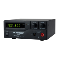
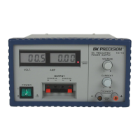
Describes power switch, controls, meters, and indicators on the front panel.
Identifies the positive and negative output terminals for variable, 12V, and 5V outputs.
Identifies power input connector, fuse holder, and DC fan on the rear panel.
Important safety warnings, electrical shock prevention, and equipment protection measures.
Detailed steps for connecting the power supply to equipment.
Instructions for setting up and operating the supply in constant voltage mode.
Procedure for setting the maximum output current limit.
Steps for setting up and operating the supply in constant current mode.
Explains the automatic crossover characteristic between CV and CC modes.
Details the specifications and connection for the fixed 12 VDC output.
Details the specifications and connection for the fixed 5 VDC output.
Explains how to use multiple outputs simultaneously and provides an example.
Instructions for connecting outputs in series to achieve higher voltages.
Instructions for replacing blown fuses, including voltage-specific fuse values.
Information on obtaining repair and calibration services from authorized agencies.
Procedure for returning the product for warranty service, including required documentation.
Procedure for returning the product for non-warranty service and payment options.
Details the duration and terms of the one-year limited warranty.
Lists conditions that void the warranty, such as misuse or unauthorized repairs.
| Output Voltage | 0 - 36 V |
|---|---|
| Output Current | 0 - 5 A |
| Power Rating | 180 W |
| Load Regulation | ≤ 0.01% + 3 mV |
| Line Regulation | ≤ 0.01% + 3 mV |
| Dimensions | 8.54 x 4.13 x 12.24 in (217 x 105 x 311 mm) |
| Weight | 9.9 lbs (4.5 kg) |
| Voltage Regulation | ≤ 0.01% + 3 mV |
| Ripple and Noise | 1 mVrms |
| Operating Temperature | 0°C to 40°C |
| Storage Temperature | 70 °C |