Do you have a question about the BK Precision 9201 and is the answer not in the manual?
Important safety precautions to follow before applying power and during operation.
Explanation of safety category ratings (CAT I, II, III, IV) based on IEC 61010.
Specifies the mains power environment and voltage requirements for the instrument.
Details the importance of safety ground connection and potential hazards.
Specifies limits for temperature, altitude, and sunlight exposure.
Guidance on handling damaged instruments, cleaning, and critical applications.
Instructions for qualified personnel on replacing fuses safely.
Notes on authorized servicing and maintaining cooling fan airflow.
Guidance on selecting wire diameter to handle current and prevent overheating.
Information regarding the disposal of waste electrical and electronic equipment.
Details standards met for CE marking related to voltage and EMC.
Explanation of hazard symbols (Caution, Warning, Danger) and their meanings.
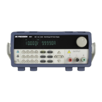
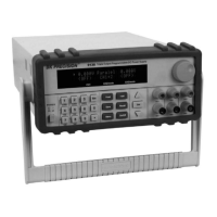
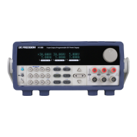
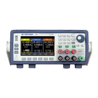
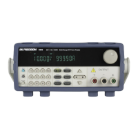
Description of the 9200 Series power supplies and their key features.
List of items included with the power supply and instructions for checking.
Physical dimensions for the 9201/9202 and 9205/9206 models.
Instructions for installing the instrument in a standard 19-inch rack.
Identification and description of all controls and indicators on the front panel.
Detailed explanation of the function of each button on the keypad.
Identification of rear panel ports including interfaces and terminals.
Explanation of the various status indicators shown on the VFD display.
Specifies acceptable AC input voltage ranges and frequency.
Warning regarding the use of appropriate and safety-certified power cords.
Table specifying the correct fuse type for each model and voltage setting.
Step-by-step instructions to select 110V or 220V operation.
Table providing recommended wire gauges based on current ratings.
Safety measures to take before connecting wires to output terminals.
Procedure to check if the AC input voltage meets requirements.
Steps to power on the instrument and initiate the self-test sequence.
List and description of possible error messages displayed during self-test.
Steps to verify the output current capability of the power supply.
Method to query the instrument's model and firmware version.
Overview of the structure and organization of the instrument's menu system.
Step-by-step guide on how to navigate and select menu options.
Procedure for setting the desired output voltage level.
Procedure for setting the desired output current level.
Explanation of the default local sense setup and its connections.
Steps to properly connect the instrument for remote sensing.
How to use the Meter/DVM buttons to view measurements.
Configuration of the maximum output voltage limit.
Procedure for setting the overcurrent protection limit.
Setting the instrument's behavior upon power-up (last state or default).
Enabling or disabling audible feedback for key presses.
Enabling or disabling the front panel rotary knob.
Setting the trigger source to manual or bus.
Procedures for saving and recalling instrument configurations.
Choosing a group (1-8) to store instrument settings.
Procedure for saving current settings to a memory location.
Procedure for recalling previously saved instrument configurations.
Configuring the timer for timed output activation.
Steps to enable the output timer function and start the countdown.
Procedure to reset all instrument settings to their factory defaults.
Activating or deactivating the list mode functionality.
Retrieving a previously saved sequence of steps from memory.
Creating or modifying a sequence of steps for list mode.
Procedure for setting the overvoltage protection limit.
Enabling or disabling the front panel buttons to prevent changes.
Information on the DVM's measurement range and accuracy.
Introduction to available remote communication interfaces (USB, RS-232, GPIB).
Pin definition diagram for the RS-232 female DB-9 interface.
Steps to configure RS-232 settings like baud rate and parity.
Requirements for USB interface configuration and NI-VISA installation.
Instructions for selecting and configuring the GPIB interface address.
Explanation of parameter formats used in SCPI commands.
Description of the four status registers used by the power supply.
Details the bit definitions for the standard event status register.
Details the bit definitions for the query status register.
Explanation of commands for clearing registers and setting event enables.
Commands to query status registers and instrument identification.
Commands for operation complete, power on control, and reset.
Commands for status byte enable, reading status byte, and trigger.
Commands for saving and recalling instrument setups.
Command to read the value in the query event register.
Command to read the value of the query condition register.
Retrieves error information from the instrument's error queue.
Gets the instrument's current SCPI version information.
Commands to switch between remote and local control modes.
Selects the communication interface (GPIB, USB, RS232).
Commands to create and manage trigger signals and sources.
Command to turn the power supply output ON or OFF.
Sets the desired output current value for the power supply.
Configures the software-based current protection level.
Sets the desired output voltage value for the power supply.
Sets a voltage value to be applied upon receiving a trigger signal.
Configures the software-based voltage protection level.
Checks and clears the overvoltage protection trip status.
Sets the maximum permissible output voltage.
Combines setting voltage and current, effective within limits.
Reads the current actual output voltage from the instrument.
Reads the current actual output current from the instrument.
Reads the current actual output power from the instrument.
Reads the latest measured value from the Digital Voltmeter.
Toggles the display between output status and DVM readings.
Sets the state of the list mode functionality (enable/disable).
Sets the voltage value for a specific step in a list sequence.
Sets the current value for a specific step in a list sequence.
Recalls a saved list file from memory.
Saves the current list file to non-volatile memory.
Answers to common issues like power-up problems and mode settings.
Guidance for resolving issues with RS-232 communication.
Specifications for output voltage, current, and power ratings.
Specifications for line/load regulation and output ripple/noise.
Specifies operating temperature, humidity, and storage conditions.
Details the physical size and weight of the instrument.
Instructions on how to obtain warranty service and return products.
Instructions for obtaining non-warranty repair services.
Details of the three-year warranty, including coverage and exclusions.
| Output Voltage | 0 - 20 V |
|---|---|
| Output Current | 0 - 5 A |
| Power Rating | 100 W |
| Ripple and Noise | ≤ 1 mVrms |
| Display | LED |
| Operating Temperature | 0 to 40 °C |
| Storage Temperature | -20°C to +70°C |
| Power Requirements | 100-240VAC, 50/60Hz |
| Load Regulation | ≤0.01% + 2mV |
| Line Regulation | ≤0.01% + 2mV |
| Voltage Regulation | ≤0.01% + 2mV |