EasyManua.ls Logo

BK Precision 9202 User Manual

BK Precision 9202
64 pages
To Next Page IconTo Next Page
Page #1 background imageLoading...
Page #1 background image
i
9200 Series
Multi-Range DC Power Supply
Models: 9201, 9202, 9205, 9206
USER MANUAL
w ww . . co m
information@itm.com1.800.561.8187

Table of Contents

Question and Answer IconNeed help?

Do you have a question about the BK Precision 9202 and is the answer not in the manual?

BK Precision 9202 Specifications

General IconGeneral
Load Regulation≤ 0.01% + 3 mV
Line Regulation≤ 0.01% + 3 mV
DisplayLED
Number of Outputs1
Output Current0 to 2 A
Ripple and Noise1 mVrms
Weight3.5 kg
Operating Temperature0 to 40 °C
Storage Temperature-20 to 70 °C
Voltage Regulation≤0.01% + 3mV

Summary

Safety Summary

General Safety Precautions

Crucial precautions before applying power and general warnings for safe operation.

Accessory Safety & Electrical Power

Grounding & Hazardous Environments

Details grounding importance and prohibits operation in explosive/flammable atmospheres or with hazardous substances.

Operating Environment & Handling

Application Restrictions & Circuit Safety

Prohibits use in life-support systems and warns against touching live circuits without qualified personnel.

Internal Hazards & Fuse Replacement

Servicing & Cooling Fan Maintenance

Advises against unauthorized servicing and emphasizes keeping cooling fans clear for airflow.

Wire Gauge & Safe Usage

Front Panel Overview

Front Panel Controls and Displays

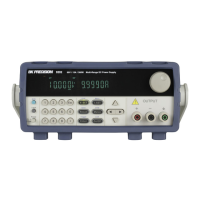
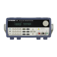
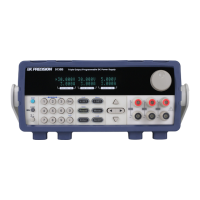
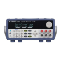
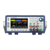
Identifies and describes the VFD display, keys, output terminals, and rotary knob.

Keypad Overview

Keypad Function Descriptions

Explains the function of each key on the keypad, including Shift, Local, Numeric, and Function keys.

Rear Panel Overview

Rear Panel Connectors and Ports

Identifies rear panel components like interfaces, power receptacle, and fuse box.

Display Overview

Getting Started

Input Power Requirements

Specifies AC input voltage range and frequency, and power cord safety.

Fuse Requirements

Line Voltage Selection

Line Voltage Switch Location

Shows location of the line voltage switch on rear/bottom panels for different models.

Output Connections

Wire Gauge for Output Terminals

Provides a table for selecting appropriate wire gauge based on current for safe connectivity.

Preliminary Check

Setup Verification and Self-Test

Steps for verifying AC input, powering on, running self-test, and understanding error messages.

Voltage Output Check

Steps to verify basic voltage output with no load connected after power on.

Current Output Check

Front Panel Operation

Menu Options Overview

Describes the structure of the menu system and its main sections.

Accessing the Menu System

Configure Voltage and Current Output

Setting Output Voltage

Instructions for setting the output voltage using the knob or keypad.

Setting Output Current

Instructions for setting the output current using the knob or keypad.

Remote Sense Compensation

Enabling Remote Sense

Voltage/Current Measurement

SYSTEM Menu

Voltage Limit Setting

How to configure the maximum voltage limit to prevent accidental changes.

Overcurrent Protection (OCP) Setup

Configure Power-On State

How to set the initial power-on state (LAST or DEFault values).

Lock/Unlock Rotary Knob

Save/Recall Instrument Settings

Recall Instrument Settings

Timer Function Setup

How to set the timer to enable output for a specified duration.

Restore Factory Default Settings

List File Editing Details

Overvoltage Protection (OVP)

Set OVP Limit

Steps to set the OVP limit to protect the power supply from overvoltage.

Disable/Enable OVP

Digital Voltmeter (DVM)

DVM Operation and Connection

How to enable the DVM, connect leads, and measure voltage.

Remote Operation

RS-232 Interface Setup

USB Interface Setup

GPIB Interface Setup

SCPI Status Register

IEEE488.2 Common Commands

Reset Command (*RST)

Recall Setup Command (*RCL)

SYSTEM Subsystem

Query Error Information (SYST:ERR?)

Command to query error messages from the power supply.

Switch to Local Mode (SYST:LOCal)

Set GPIB Address (SYST:COMM:GPIB:RDEV:ADDR)

Select Trigger Source

SOURCE Subsystem

Command to control the power supply's output state (ON/OFF).

Set Output Timer State

Set Output Timer Time

Set Output Current Level ([SOURce:]CURRent[:LEVel])

Set Software Current Protection ([SOURce:]CURRent:PROTection)

Set Output Voltage Level ([SOURce:]VOLTage[:LEVel])

Set Output Voltage Level (VOLTage {<volts>|MIN|MAX|UP|DOWN|DEF})

Alternative command to set output voltage level using various options.

Set Software Voltage Protection ([SOURce:]VOLTage:PROTection)

Query OVP Trip State (VOLT:PROTection:TRIP?)

Set Output Voltage Limit ([SOURce:]VOLTage:LIMIt)

Apply Voltage and Current ([SOURce:]APPLy)

Command to set voltage and current simultaneously.

MEASUREMENT Commands

Query Output Voltage (MEASure[:SCALar]:VOLTage[:DC]?)

Command to query the actual output voltage.

Query Output Current (MEASure[:SCALar]:CURRent[:DC]?)

Command to read the actual output current.

LIST Commands

Troubleshooting Guide

Power-Up Issues

Addresses problems related to not being able to power up the supply.

Constant Current Mode Setup

Explains how to set up the supply to run in constant current (CC) mode.

RS-232 Communication Issues

Troubleshooting steps for RS-232 response problems, including CR/LF and settings.

Specifications

Service Information

Limited Three-Year Warranty

Warranty Coverage

Details the warranty period, coverage, and what is included in the warranty.

Related product manuals