Do you have a question about the BK Precision 9116 and is the answer not in the manual?
Defines IEC 61010 safety category ratings for electrical environments.
Guidance on WEEE directive for product disposal in the EU.
States compliance with the Low Voltage Directive and relevant standards.
States compliance with the EMC Directive and relevant standards.
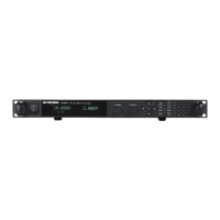
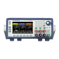
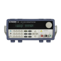
Introduces BK Precision models 9115, 9115-AT, 9116 power supplies and their features.
Lists items included with the power supply upon purchase.
Provides physical dimensions of the power supply in mm and rackmount size.
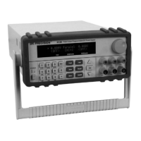
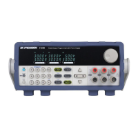
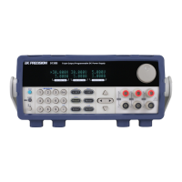
Illustrates and describes the front panel controls and indicators of the instrument.
Detailed explanation of each control and indicator on the front panel.
Illustrates and describes the rear panel interfaces and connections of the instrument.
Detailed explanation of each interface and connector on the rear panel.
Explains the VFD display layout and status indicators.
Provides a detailed breakdown of each indicator and symbol on the display.
Details AC input voltage, frequency, and fuse requirements for powering the instrument.
Specifies the AC input voltage and frequency range the supply accepts.
Details the specific AC input fuse required for the instrument.
Step-by-step instructions for checking and replacing the AC input fuse.
Describes the rear panel DC output terminals and recommended wire gauge.
Steps to verify AC input voltage and perform an initial self-test.
Lists potential error messages during self-test and their meanings.
Procedures for verifying basic voltage and current output.
Procedure to check basic voltage output without a load.
Procedure to check basic current output by shorting terminals.
Steps to view the instrument's model and firmware version.
Outlines the structure and sections of the instrument's built-in menu system.
Provides instructions on navigating and accessing the instrument's menu system.
How to set the output voltage and current using front panel controls.
Instructions on how to set the output voltage using the front panel controls.
Instructions on how to set the output current using the front panel controls.
Explains how to use remote sense for voltage compensation.
Describes the default local sense configuration and wiring.
Configuration for Over Voltage Protection (OVP) and Maximum Power Limit.
Steps to set the Over Voltage Protection (OVP) limit and delay time.
Instructions for setting the maximum power output limit to protect the device.
Access to system settings like factory defaults, power-on state, and trigger.
Procedure to reset all instrument settings to their factory defaults.
How to configure the instrument's state upon power-up.
How to set the trigger source for initiating program sequences.
How to save and recall instrument configurations to/from memory.
How to choose a memory group for saving or recalling settings.
Steps to save the current instrument settings to memory.
Steps to recall previously saved instrument settings from memory.
How to turn the front panel key beep sound on or off.
Overview of available interfaces for remote communication and setup.
Configuration steps for RS-232 serial communication for remote control.
Configuration steps for USBTMC communication for remote control.
Connection details for the GPIB interface.
Pinout and connection details for RS-485 serial communication for multi-unit control.
Configuration for automatic display switching between setting and measured values.
Access to configuration settings like load setup and analog control.
How to enable the internal dummy load for faster voltage fall time.
How to control and monitor the output using external DC sources.
Steps to configure the analog interface for monitoring voltage and current.
Steps to configure the analog interface for voltage and current programming.
How to select between voltage or resistance sources for external control.
How to disable external analog control when not in use.
Details the pin assignments for the analog interface connector.
How to control the output ON/OFF state via the analog interface.
How to use the analog interface for emergency shutdown of the output.
How to monitor the power supply status via analog interface outputs.
How to monitor the operating mode (CV/CC) via analog interface outputs.
How to set output voltage and current via analog interface inputs.
How to monitor output voltage and current via analog interface inputs.
How to set minimum and maximum voltage limits for protection.
How to connect multiple units in series or parallel for increased output.
General guidelines for connecting and setting up units in series/parallel.
Specific instructions for making parallel and series output connections.
How to configure one unit as Master and others as Slave for multi-unit control.
Steps to configure the master/slave relationship after physical connection.
Introduces the List mode for creating and running programmed sequences.
How to define voltage, current, width, and slope for each step in a sequence.
How to group sequences into programs and set repeat times.
How to recall stored programs and trigger their execution.
Steps to recall a stored program from memory.
Steps to execute a recalled program sequence.
Details automotive-specific test functions available on the 9115-AT model.
Configuration and parameters for the DIN 40839 automotive test standard.
Overview of ISO 16750-2 automotive test simulations.
Setup for the Short Voltage Drop test simulation under ISO 16750-2.
Setup for the Profile for Reset test simulation under ISO 16750-2.
Setup for the Starting profile test simulation under ISO 16750-2.
How to set the rise and fall times for output voltage transitions.
How to enable or disable the front panel key lock function.
Details on connecting to the instrument via RS-232, GPIB, RS-485, and USBTMC.
Pinout and connection details for RS-232 serial interface.
Connection details for the GPIB interface.
Pinout and connection details for RS-485 serial communication for multi-unit control.
Connection details for the USBTMC interface.
Overview of SCPI and instrument-specific commands for remote control.
Frequently asked questions regarding general operation and issues.
Troubleshooting common problems with remote communication.
Specifies operating and storage conditions, including humidity and temperature.
Instructions for obtaining warranty service and returning the product.
Instructions for non-warranty service and repair charges.
| Brand | BK Precision |
|---|---|
| Model | 9116 |
| Category | Power Supply |
| Language | English |